50MHz 3EL ZLスペシャルアンテナ
50MHz 3EL ZL special antenna
(Last updated June 24, 2023)
|
Work on the 50MHz 2-element ZL special antenna, which had been suspended since the end of last year due to the cold weather, was hastily restarted in April and finally completed. At the end of the 2-element section, I posted a preview image of a 3-element antenna, but I continued to consider upgrading it to a 3-element antenna.
By the way, if you've seen the corner for the first 2-element ZL Special antenna, did you notice that the elements are much shorter than those of an antenna using a regular aluminum pipe? For example, the Comet CA-52HB (2EL HB9CV), which operates in a similar way, has an Ra (secondary antenna) length of 2.72m, while for the ZL Special it is 2.50m (300 ÷ 51MHz × 0.85 ÷ 2 = 2.5m). The difference is 0.22m (22cm).
This is due to the difference in the shortening rate of the material used for the element. In the case of the Comet antenna, an aluminum pipe is used, and in the case of the ZL Special, as you know, a 300 Ω feeder line is used. Calculating the shortening rate of the aluminum pipe backwards from the element length of the Comet HB9CV antenna mentioned above, we get 2.72 m ÷ (300 ÷ 51 MHz ÷ 2) = 0.92 (92%). However, this is the shortening rate when using an aluminum pipe with a diameter of 10 mm, and the shortening rate will naturally change if the pipe diameter is different.
On the other hand, the shortening rate of the 300Ω feeder wire is 0.85 (85%), as published by the manufacturer. This difference in shortening rate results in a difference in element length of 22 cm. The shortening rate of the 300Ω feeder wire was published on the website of Oyaide Electric, the distributor of the 300Ω feeder wire introduced in this section.
If you want to make it as small as possible due to installation conditions or other reasons, you can insert a shortening coil or similar. This certainly reduces the antenna size, but it also means that the antenna's performance (front gain, resonance band, etc.) will be significantly reduced. This shortening ratio of 0.85 (85%) is not as high as the 0.67 (67%) of a coaxial cable, but it is still a pretty good shortening ratio. When making a full-size antenna, it is best to make it as small as possible. In that sense, the ZL Special, which uses a 300Ω feeder line with a large shortening ratio, is more advantageous.
Furthermore, the 300Ω feeder wire has a folded structure with two core wires arranged in parallel. In the past, folded dipole antennas using this 300Ω feeder wire were said to have a wide resonant band. For this reason, the ZL Special antenna, which uses this feeder wire, also resonates over a very wide band, just like many others. Antennas that resonate over a wide band require fewer antenna couplers, making them very easy to use.
I've praised the ZL Special quite a bit, but it does have one drawback. The resonant frequency drops significantly when exposed to rain. In my case, I designed it to resonate at a slightly higher frequency, around 51 MHz, so even when it got wet in the rain, I was able to use it without any problems at around 50 MHz.
In any case, the 50MHz band is a band where it is relatively easy to build a multi-element antenna, since the element length on one side is only about 1.5m. For this reason, I had no intention of operating with the previous 2-element antenna, and wanted to start operation with at least a 3-element antenna. So, I would like to introduce the 3-element antenna that I am currently prototyping.
| Element data currently being prototyped
|
Now that the base 2-element antenna is complete, it can be easily made into a 3-element antenna by simply adding one more element. So, I used the familiar MMANA to examine this. The result was the element data shown in the table below.
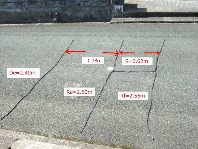
For simplicity's sake, I used the 2-element data as is. I added a director (De) and set the distance between the secondary emitter (Ra) and director (De) to 1.38m. In this state, I tried to find the length of the director (De) that would maximize the front gain.
The 1.38m distance between De and Ra was determined by subtracting the 0.62m distance between the Ra (secondary launcher) and Rf (reflector) from the 2m distance of the VP25 (the VP30 is thicker and sturdier), which is sold as a standard length. When calculating the distance between De and Ra using MMANA, the wider the distance, up to about 1.5m, the greater the front gain. However, since the total length of the boom is limited to 2m, we set it to 1.38m, as this is the length that fits within that.
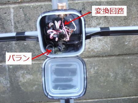
This method is the height of shortcuts, but I chose it because I wanted to complete the prototype quickly (since the condition is about to be improved, I wanted something that could be used immediately). Since this is data that was quickly created, the front gain and F/B ratio are not figures that I would recommend. Also, I forgot to remove the 75Ω:50Ω conversion circuit that was included in the two-element amplifier, so it is still included.
Experimental results from other stations have reported that the impedance at the feed point has decreased by converting to a 3-element configuration. For this reason, it is interesting to see what characteristics will be obtained if the 75Ω:50Ω conversion circuit is removed. The results of removing the conversion circuit are shown below in this section.
If I reconsider in detail the length and spacing of the three elements De, Ra, and Rf, I think I can come up with something with a better front gain and F/B ratio. I plan to reconsider this in the future when I have time. Anyway, I made a prototype using the data in the table below.
This page also contains the progress of various experiments. If you would like to actually make one, we have introduced several patterns at the end of this page, rather than the prototype data immediately below. We recommend that you use these as a reference and choose the one that you think is best for you to make your own, or use them as a reference and create your own using new data that you have created yourself.
 300Ω feeder wire sales site Oyaide Electric homepage
The calculation results for the above element data are linked below. If you are interested, please right-click on the file below and select "Save link as" to download the MAA file. If you open the downloaded MAA file in the MMANA software, you can see the detailed calculation results for the antenna.
Download 50MHZ 3EL.MAA
MMANA software (MMANA for Windows Ver. 1.77) download site
JE3HHT Mori OM's homepage
*Click on each photo to see an enlarged version.
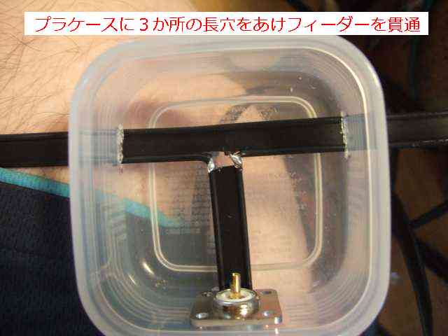
Make three holes in the plastic case and
pass the feeder wire through them. |
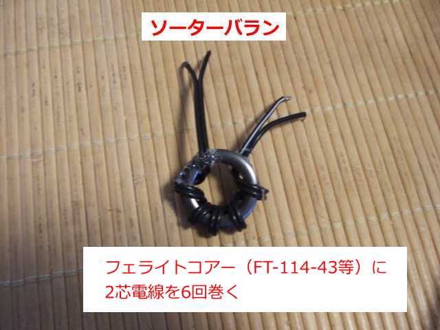
Make a sorter balun by winding two-core wire
six times around an FT-114-43 or similar. |
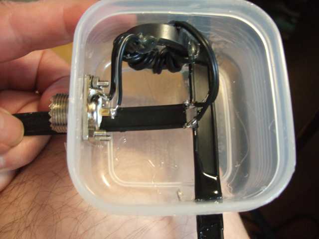
Place a sorter balun between
the connector and the feeder wire |
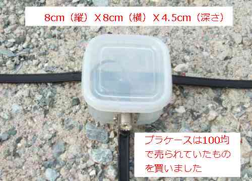
Put the lid on the plastic case and finish it
Finally, wrap it with tape to make it waterproof. |
 |
 |
 |
 |
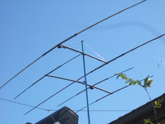
Regarding the support members for the elements, in the previous 2-element model, I tried making one by bundling two 6mm corrugated poles together (1.3m of the 2.1m total length was used on one side, leaving the remaining 0.7m bundled together), and also tried making a prototype using only 8mm corrugated poles, but both had noticeable curvatures, so in the end I ended up making it by combining PVC pipe VP13 and 6mm corrugated poles.
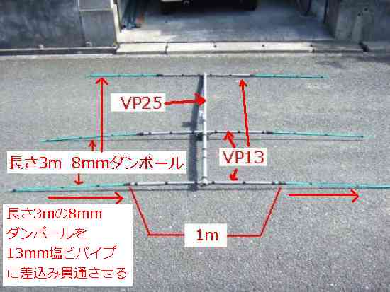
Additionally, to attach the VP13mm PVC pipe (inner diameter 13mm, outer diameter 18mm) that supports the element to the boom, we previously used a high-quality product called DevMount , as we had some on hand . This time, we drilled an 18mm diameter hole in the VP25mm (30mm) PVC pipe used for the boom, and passed the VP13mm (outer diameter 18mm) PVC pipe through it. This method eliminates the need for clamps and is inexpensive. I think it would be good to make two-element systems this way as well. We also used hot glue to bond the boom and 13mm pipe.
This time, I used a VP25mm boom, but the boom bent in the intense summer heat. I think it would be better to upgrade to a VP30mm, which is one size larger. Even with the VP30mm, the boom may still bend, so ultimately it may be a good idea to use nylon rope or stainless steel wire to lift both ends of the boom.
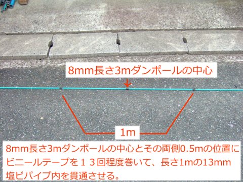
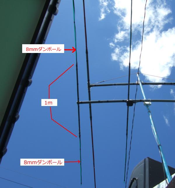
The VP13mm PVC pipe used was cut into three 1m pieces (for De.Ra.Rf), and a 3m length of 8mm corrugated cardboard was placed directly inside each of the VP13mm pipes. However, since there would be gaps if the cardboard were to be inserted through the pipe, we wrapped vinyl tape around 13 times around the center of the cardboard and at 0.5m positions on both sides (a total of three places) to adjust it so that it would fit perfectly inside the pipe. By doing this, the 8mm corrugated cardboard is placed inside the 1m length of VP13mm, reinforcing it and also preventing the VP13mm from bending.
The support pipe section is completed by attaching these 1m long VP13mm cables to the designated positions for De, Ra, and Rf. Please see the photo below to see the finished state of the support pipe. All that remains is to secure the element made from the 300Ω feeder wire to the assembled support pipe with vinyl tape, and the 3EL ZL Special is complete. Below are photos showing the state of each part.
※*Click on each photo to enlarge it.
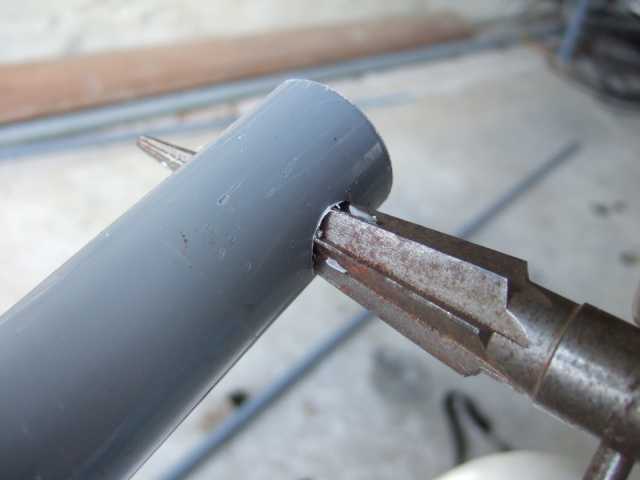
The hole in the boom was enlarged with
reamer so that the VP13 could pass through. |
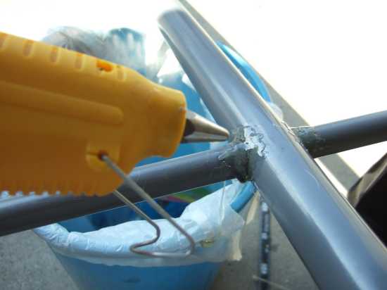
Insert 1m long VP13 into the boom in
three places and fix with hot glue. |
Wrap tape around the center and 0.5m on
both sides of a 3m long cardboard pole. |
 |
 |
 |
Insert the dam pole into the VP13mm
to complete the element support unit |
Attach the feeder wire to the support unit
with vinyl tape to complete the installation.
|
A close-up of the secondary launcher
and reflector.A slim and sleek finish. |
 |
 |
 |
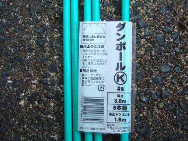
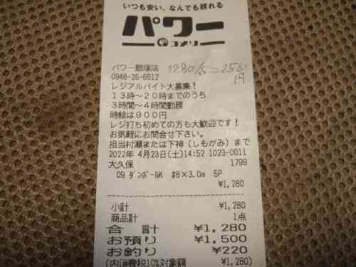
The cardboard poles used to support the elements (8mm thick, 3m long) are sold at Power Komeri for 1,280 yen for a set of 5. Power Komeri is a nationwide home improvement store, so I think they are sold in every region. If they are not sold there, I think they can be ordered if you ask.
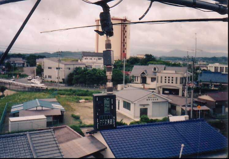
| SWR measurement result of the completed antenna |
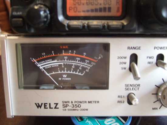
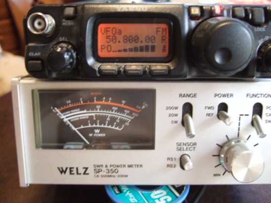
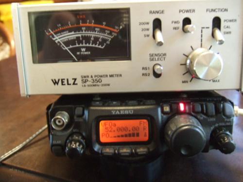
The ZL Special Antenna was completed by combining an element support unit made from a PVC pipe and a cardboard pole with an element made from a 300 ohm feeder wire. I then measured the SWR by transmitting radio waves onto the antenna. The measurement results are shown in the photo below.
*Click on each photo to enlarge it.
50.005MHZの測定中
SWR=1.05 |
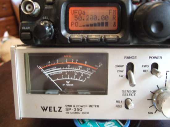
50.200MHZの測定中
SWR=1.05 |
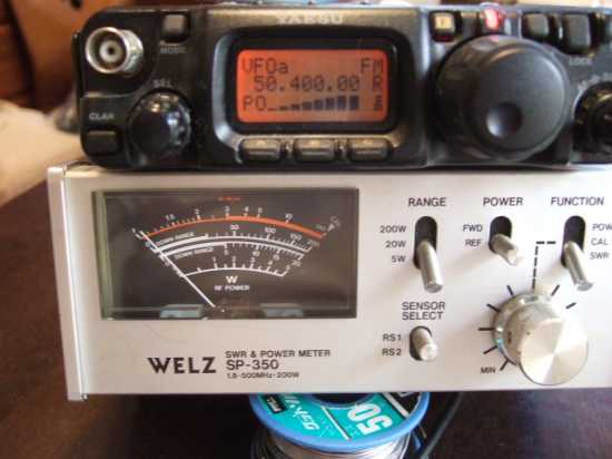
50.400MHZの測定中
SWR=1.06 |
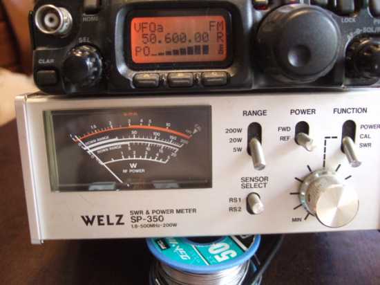
50.600MHZの測定中
SWR=1.06 |
 |
 |
 |
 |
50.800MHZの測定中
SWR=1.07 |
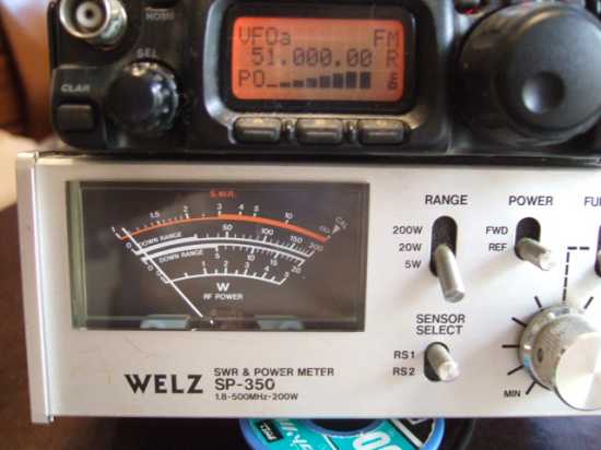
51.000MHZの測定中
SWR=1.09 |
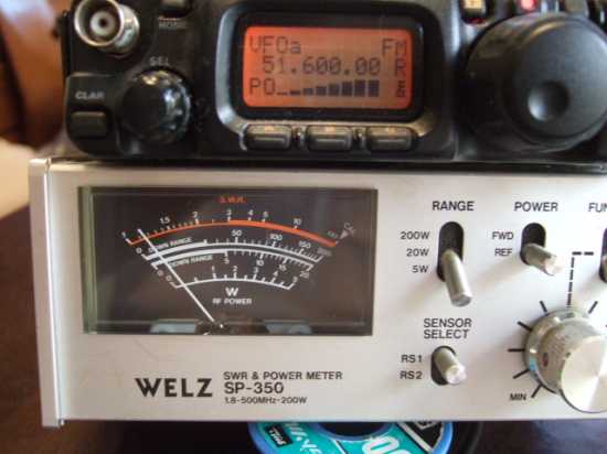
51.600MHZの測定中
SWR=1.15 |
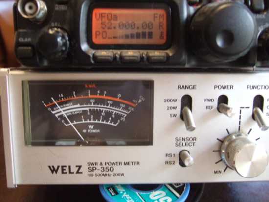
52.000MHZの測定中
SWR=1.21 |
 |
 |
 |
 |
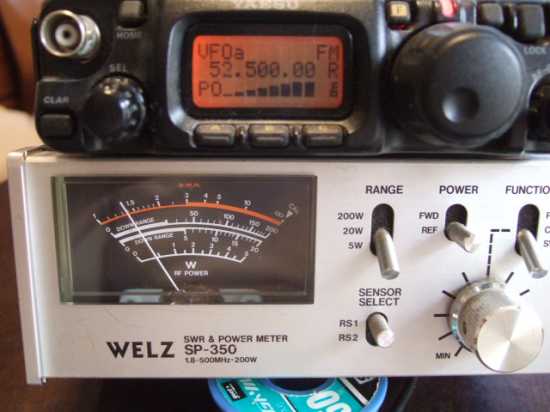
52.500MHZの測定中
SWR=1.39 |
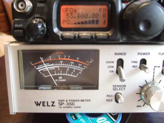
53.0000MHZの測定中
SWR=1.48 |
53.500MHZの測定中
SWR=1.50 |
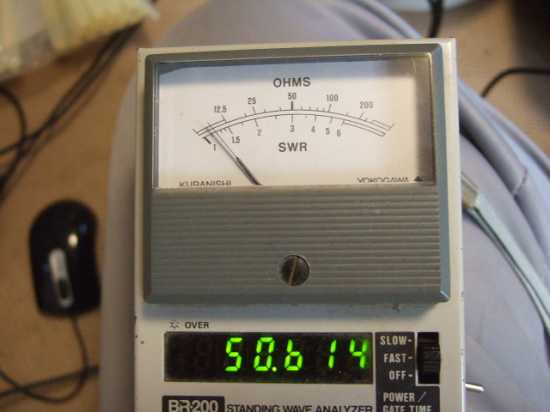
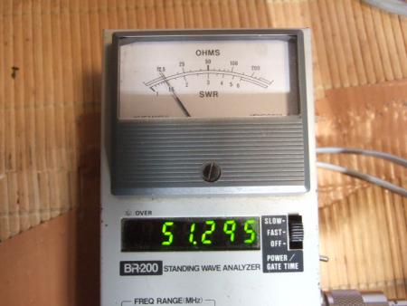
共振周波数は50.614MHZ |
 |
 |
 |
 |
Looking at the measurement results, there was very little reflection over a fairly wide bandwidth, which made me think, "Is that really true?" I'm not sure why, but since I was measuring at a low power output of about 5W, there was no reflected wave power, and on top of that, there was a 75Ω:50Ω conversion circuit, which I think also attenuates the reflected wave, causing the apparent SWR value to appear low.
I began to think that the measurement method using a low-power SWR meter like this one might not be providing accurate values. Also, the photo shows the resonance frequency (50.614MHz) measured with the BR-200 analyzer, but normally the SWR value would drop near the resonance frequency, but the measured SWR characteristics showed no signs of this.
Furthermore, when measuring the resonant frequency of this BR-200 (Kuranisi), there was a difference in the frequency that dipped when the frequency-changing dial (the volume for changing the voltage of the varicap) was turned clockwise or counterclockwise, and the values were different by around 100 kHz each time I measured.
On a different note, the transceiver I'm currently using, the FT-817, is designed to reduce its output power to protect the final stage circuit when an antenna with a high SWR is connected. Even at the upper limit of 54MHz, as far as I can tell from my pass-through power meter, it doesn't appear to be reducing the power, so in that sense, there's no need to use an antenna coupler within the band, and this antenna may still be usable.
However, I was still concerned about this, and there was also the backlash problem with the BR-200, so I started looking for a good measuring instrument that could measure SWR over a wide frequency range. It seems that high-quality instruments cost around 50,000 yen, but I don't want to buy such an expensive measuring instrument at this point.
Just then, when I was browsing Amazon for another reason, a product information screen popped up saying, "Here's what we have, would you like to buy it for your husband?" It seems that they've recently built a system that determines what a person wants based on their browsing history, and it pops up product information that suggests they'll probably buy it.
Among them was the NanoVNA Antenna Network Analyzer, priced at 5,380 yen. I thought, "What on earth is this? Given the price, it's bound to be pretty useless." Still, I was intrigued (and fell prey to the enemy's strategy), so I looked into it more closely. It turns out it has an ultra-wideband measurement range, stretching from 50 kHz to 1500 MHz. My BR-200 can only measure up to 170 MHz, so it seems like it could be used in the 400 MHz and 1200 MHz bands, too. It also seems capable of a variety of measurements, including measuring the bandwidth of filters and the length of coaxial cables, in addition to measuring antenna SWR. So, I concluded that it was a great value for the price, and worth giving it a try.
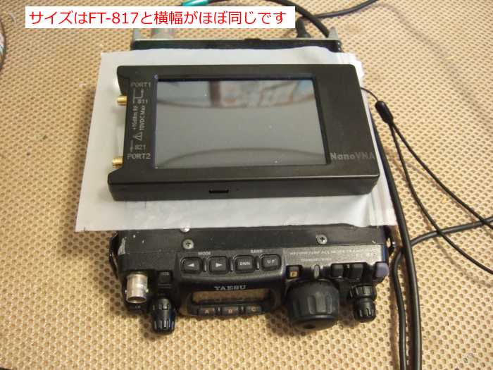
As you can probably guess from this story, I ordered the NanoVNA-H4 antenna network analyzer. This is a major deviation from the original ZL Special story, but to continue talking about this analyzer a little more, the NanoVNAs in the low-priced group sold on Amazon are roughly divided into three groups based on selling price.
The one priced at 5,380 yen has a sandwich-structured circuit board made of two layers, with no side covers . Next, the one priced at 6,780 yen is the 5,380 yen model housed in a special case . Both the 5,380 yen and 6,780 yen models have a display size of 2.8 inches. The last one is priced at 9,980 yen. This is called the NanoVNA-H4, and has a display size of 4 inches, which is slightly larger and easier to see.
There is no difference in performance between the two products, and the price seems to depend on whether they are in a case or not, and whether the screen size is 2.8 inches or 4 inches. I've been having trouble seeing small objects lately, so I splurged and ordered the NanoVNA-H4 for 9,980 yen.
NanoVNA 5,380 yen on Amazon site
NanoVNA 6,780 yen on Amazon site
NanoVNA-H4 on Amazon site *The price skyrocketed for a while, but it seems to have settled down a bit.
The product arrived yesterday and I am currently learning how to use it. There are many videos on YouTube about how to use NanoVNA, so if you are interested, try searching for "NanoVNA" on YouTube.
The measurement results are now displayed. The SWR characteristics are displayed in graph form, so the characteristics are clear at a glance. As expected, the SWR value displayed is about 0.2 higher than the measurement results using low power and SWR. The NanoVNA produces a more realistic SWR curve. The screen settings are set to display only SWR. If you change the setting, a Smith chart will also be displayed on the screen.
The horizontal axis is frequency, with a center frequency of 50 MHz and a bandwidth of 6 MHz (47 MHz to 53 MHz, with each scale representing 1 MHz), and the vertical axis is set to display SWR values at 0.1 scales. Therefore, the first horizontal line from the bottom is the SWR 1.1 line, and the top horizontal line is the SWR 1.8 line. The yellow mark is a marker, and the frequency at that position is displayed in the upper right corner, and the SWR value at that time is displayed in the upper left corner of the screen. The position of this marker can be moved left and right using the dial in the upper right corner of the meter body.
*Click on the photo below to enlarge it.
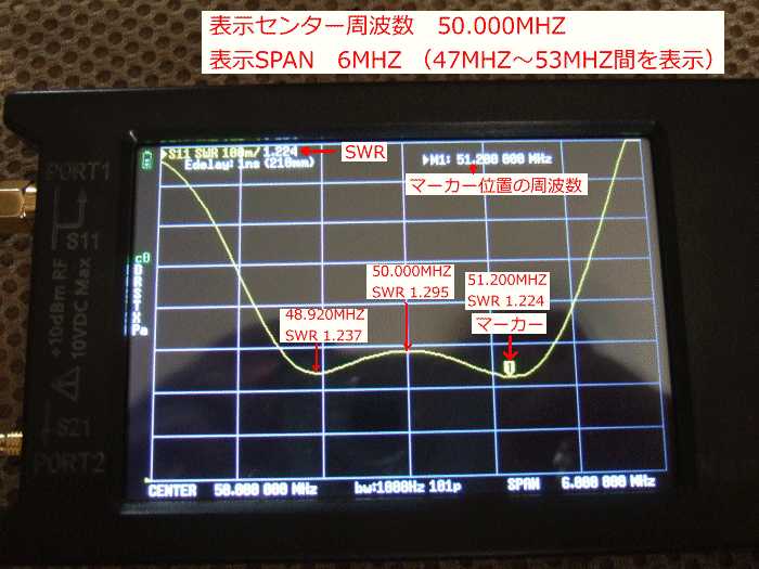
The NanoVNA display shows a curve that resembles an upside-down hump on a camel's back. I had noticed two dips when I measured with the Kuranishi analyzer BR-200 that I had been using previously. Looking at the graph like this again, I can clearly see the difference.
Why do two resonances appear? The ZL Special connects two folded dipoles (folded dipoles), Ra and Rf, in opposite phase (twisted 180 degrees). Although the two elements are in opposite phase, they are directly connected, so it is thought that the resonance frequency of each folded dipole has an effect. In this way, it is thought that two resonance points appear with phase-shifted power-feed type antennas (such as the ZL Special and HB9CV). (This is just my own speculation, so I may be wrong.)
As I moved the marker position, I noted down the frequency and SWR value at that time, and then overlaid it on the SWR curve shown above. Compared to the graph using an SWR meter, the NanoVNA displayed slightly higher SWR values overall. However, the SWR remained within 1.3 between 50,000 MHz and 51,800 MHz, so it was a decent result. I think the SWR values on the curve using the NanoVNA are more accurate.
Also, when measuring with an SWR meter, no dip was observed around the antenna's resonance point of 50.6MHz, but with the NanoVNA, there was a slight dip. In this respect, I felt that the NanoVNA more accurately represented the antenna characteristics.
We installed it on the bottom of the 21MHz 2EL and it became rotatable, so we checked the antenna performance with the cooperation of local station JA6LPP. First, we rotated the antenna to the position where we could receive the maximum signal. The signal was too strong in that position, so we reduced the power on our side and started measurements when the S meter on JA6LPP's receiver had a maximum deflection of 8.
First, I compared it with a 2EL ZL Special antenna for 21MHz. For some reason, 50MHz signals were picked up by the 21MHz ZL Special. The other station, JA6LPP, had the same problem, and he said that 50MHz signals were being picked up by a multi-band antenna that could be used for 21MHz. So I sent a 50MHz signal through a 2EL ZL Special for 21MHz and got a signal report.
The signal report was S6. So I replaced the antenna with the 3EL ZL Special I made and got another signal report, which was S8. The difference is 2. The 21MHz antenna is 2EL and the 50MHz antenna is 3EL, so I'm not sure if this is due to the difference in the elements, or whether it's because the antenna was originally used for a different frequency and was used at the original frequency.
Next, I got a signal report while rotating the antenna. I got a signal report every 45 degrees from the front. The results were S8 at the front, S6 at a 45-degree rotation, and S5 at 90 degrees (side). The report said that the signal could be detected up to 135 degrees from the side (90 degrees straight to the side), but further back, the signal was buried in nearby noise (perhaps from a large solar power generation facility?), making it difficult to detect.
So, I had a general idea, but on another day I rotated the antenna while receiving a signal from a location about 500m away, plotting the S-meter readings every 22.5 degrees and drawing a pattern diagram. The result was as shown in the pattern diagram below. The background is shifted to the left, which is probably due to the influence of a two-story house on the right side.
However, in this case, the antenna is only 6m above ground level on the roof of a garage, and all the buildings to the right are two-story, so the antenna is lower than the two-story buildings, making it a very noticeable environment. Given these circumstances, it's impossible to get a decent pattern diagram. That said, there is no difference between the front and back (the ZL Special I built after looking at an antenna handbook when I first started broadcasting showed no difference lol), and for now it seems to be working as a beam antenna.
The pattern seems somewhat similar to the one shown on the right below, calculated by MMANA. The back side is shifted to the left, which is likely due to the influence of the two-story building on the right side of the antenna. MMANA's calculations show an F/B ratio of 11.32dB. Actual measurements show that the front and back signal strengths are S=9 for the front and S=6 for the back, with a difference of 3 on the S meter. Assuming one notch on the S meter is 3dB, then the F/B ratio would be about 9dB. When actually receiving the signal, it seemed like the back signal was a little too weak.
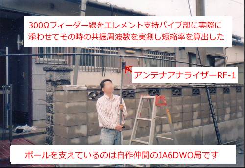
I used the same method to draw the pattern when I made a 3-element ZL special for 21MHz around 1995, but at that time the antenna was mounted on a concrete pillar 12m above ground, with an unobstructed 360-degree view, as shown in the photo below. This resulted in a relatively clean pattern as shown below.
*Click on the image below to enlarge it.
| Remove the 75Ω:50Ω conversion circuit and measure again |
This is a continuation of my long-awaited experiment with a 50MHz 3EL antenna. Last time, I forgot to remove the 75Ω:50Ω converter, leaving it attached and converting it to 3EL. I read an article about another station's experiment results that showed that converting to 3EL reduced the impedance at the feed point. Given this, I thought there was no need for the 75Ω:50Ω converter, so I removed it and remeasured the resonant frequency and SWR.
The results were as follows. As far as the SWR meter is concerned, the SWR is flat at almost 1.1 up to around 52MHz. However, the SWR value deteriorates sharply at the 53MHz boundary. On the other hand, with the converter circuit installed, the SWR remained within 1.5 up to 53.5MHz. Note that the photo below only shows results in 1MHz increments, but in reality, SWR was measured in 100KHz increments and the SWR curve was drawn using those actual values.
It depends on how you look at this difference, but the conclusion is that the 75Ω:50Ω conversion circuit is not necessary. If you have built your amp as described here, try removing it and measuring the SWR again. If you get the same results as me, it may be better to remove it, as there will not be a significant change.
The removed 75Ω:50Ω conversion circuit can be reused as an impedance conversion circuit for a dipole antenna. The feed point impedance of a dipole antenna is said to be approximately 73Ω. For this reason, when feeding with a 50Ω coaxial cable, the internal angle of both elements is changed from 180° to about 120° to match the impedance difference.
If it is difficult to adjust the angle in the installation environment, adding this conversion circuit will eliminate the need to change the angle to adjust it. If you have already made a conversion circuit and removed it this time, I think you can use it in this way.
By the way, as you can see in the photo below, the 50MHz ZL Special had a slight bend in the boom from the beginning, but the heat this summer has made the boom bend worse. The 21MHz one is suspended with stainless steel wire, so there is no bend, but it may be better to suspend this 50MHz 3-element ZL Special with a wire as well.
*Click on each photo to enlarge it.
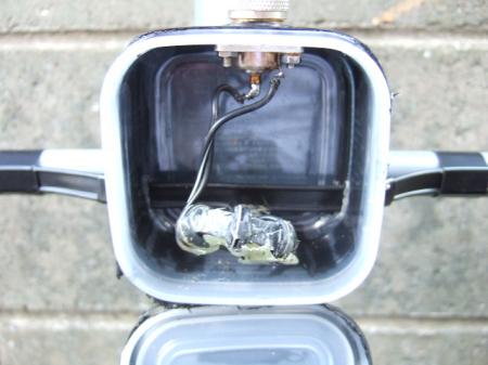
Before removing the
75Ω:50Ω conversion circuit |
75Ω: 50Ω conversion circuit
removed. Sorter balun remains. |
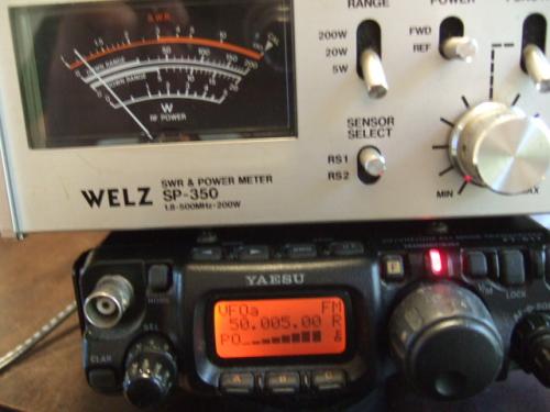
SWR=1.15 during
measurement at 50.005MHz |
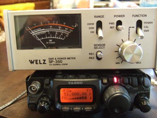
SWR=1.10 during
measurement at 51.000MHZ |
 |
 |
 |
 |
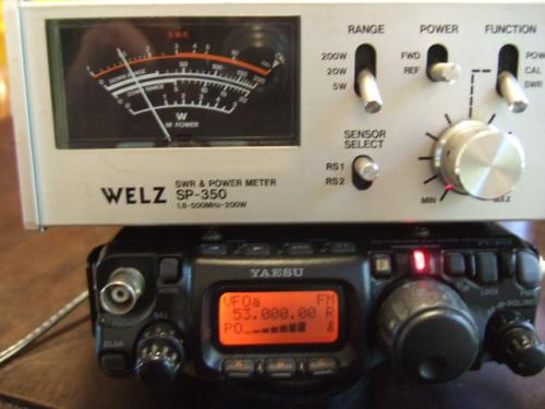
SWR=1.10 during
measurement at 52.000MHZ |
SWR=1.49 during
measurement at 53.000MHZ |
When I measured the resonant
frequency,it was about 700KHZ higher? |
Installed
under 21MHz ZL Special |
 |
 |
 |
 |
We also performed measurements using NanoVNA at the same time, but the results were not particularly worth showing, so we will not post them here. For the 50MzZ3EL ZL special antenna, we repeated calculations with various changes to the element data, aiming for a front gain of 7dBd and an F/B ratio of 18dB, but we were unable to obtain results that met our targets.
For the multi-element ZL Special, I was unsure how to input the director shape and element diameter, so I entered the values I thought would probably be fine for the current setup and performed the calculations. Therefore, I have doubts about the accuracy of the calculation results for the front gain and FB ratio.
| Remove the director and check the front gain |
I added a director to the 2EL to convert it to a 3EL, and the MMANA calculation showed a front gain of 5.46dBd. The gain of the previous 2EL was 4.42dBd, so the gain difference is only 1.04dBd.
In the case of manufacturer-made antennas, the gain difference between 2EL and 3EL is about 3dBd, so even if it is poorly made, it is unlikely that the difference would be about 1dBd. It seems that there was an error in the way the director data was entered, resulting in an error in the calculation results.
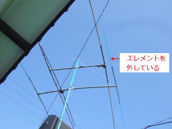
I wondered if there was any way to check this, so I tried removing the director to see what would happen. Removing the director is super easy, as it only requires removing the 300Ω feeder wire, leaving the element support pipes in place. The specific measurement method was to check the S-meter deflection in advance with the 3EL setting, and then check how the S-meter deflected with the director removed.
Station JA6LPP, who always helps us collect antenna data, joined us again this time. First, we sent out a signal at 3EL and asked JA6LPP to check the S meter on his receiver (FT-817). At this time, the signal was 9+ at 5W output, which made it impossible to make a detailed comparison, so we reduced our power to 0.5W and it read S5. Furthermore, our station and station JA6LPP are about 4km apart in a straight line, and since we both live on high ground, our positioning is easy and there are no tall buildings or other obstacles along the way.
So on another day, I removed the 3EL director and received another signal report at 0.5W output, which showed S4. Incidentally, the antenna used by JA6LPP to receive the signal was a non-directional discone antenna both before and after the change.
So the difference in the S meter was one division (S5 → S4). When I looked at the S meter scales of the manufacturers' receivers, it seemed that each company (Yaesu, Icom, Kenwood) had one division equal to 3dB.
From the above results, since the difference in the S meter reading when the director was removed was one division, it means that there is a difference of 3 dBd between 2EL and 3EL. The computer calculation results showed a difference of only about 1 dBd, but in reality it seems that the gain has increased by about 3 dBd.
*Click on each photo to enlarge it.
The element support pipe remains,
but the element has been removed. |
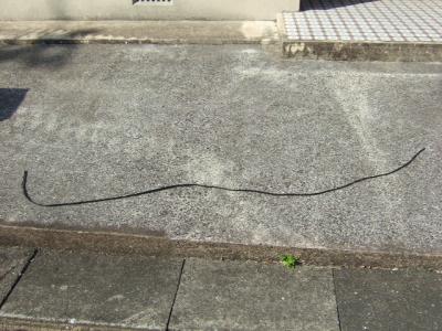
外した導波器エレメントの300Ω
フィーダー線、そのうち元に戻します |
 |
 |
So, while MMANA's calculations show that the front gain of the 3ELZL Special is 5.46dBd, in reality it seems to be about 7dBd, which is the gain of the 2EL (about 4dBd) + 3dBd. In any case, there is no doubt that the gain is higher than the 2EL. For these reasons, if you were to build one, I would still recommend the 3EL.
| I changed the length of the element |
In the last update, I pompously stated that the front-to-back ratio was not very good, but that with an antenna of around 3EL, emphasis should be placed on front gain rather than front-to-back ratio. That being said, it's a very satisfying feeling to see the S meter drop smoothly when you turn the antenna. This is also the moment when you realize that it's a beam antenna. Even though front gain is prioritized, I was wondering if the front-to-back ratio could be improved a little more.
I had some free time, so I looked into modifying the 3EL ZL Special. When I ran the calculations using the sample ZL Special, I got good results up to 2EL. However, when I ran the calculations using the ZL Special at 3EL, I didn't get the results I expected.
Therefore, I decided to use the same out-of-phase feed type HB9CV for the calculations when considering modifications. In this case, the element diameter to be input was assumed to be 10mm in diameter (5mm radius) because the distance between the two cores of the 300Ω feeder line was about 11mm. In fact, I used the same method when I built a 21MHz 3EL ZL Special around 1995.
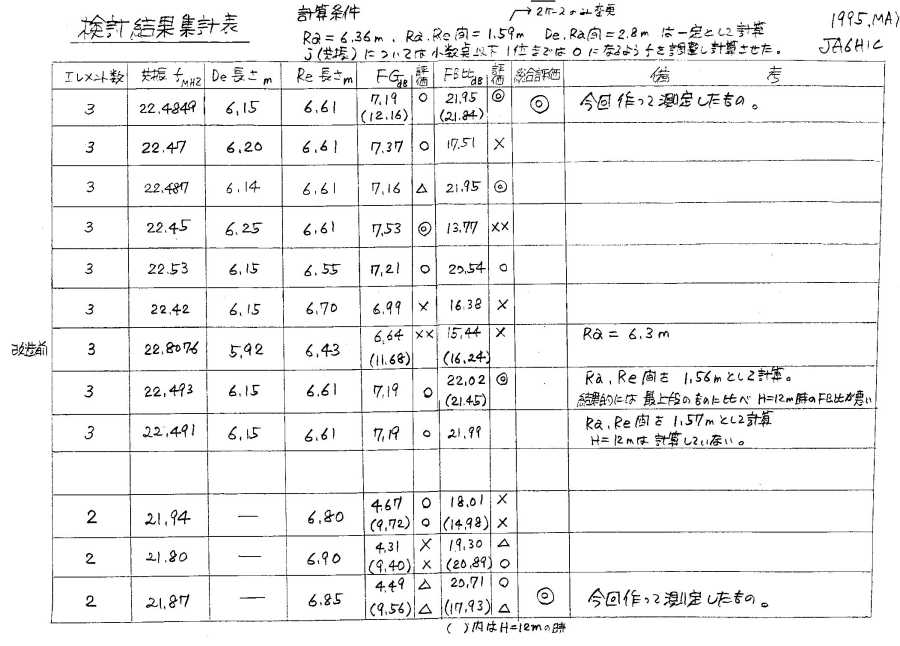
The calculation software I was using at the time was MMPC (created by JA1WXB Matsuda OM), and since there was no sample data for the ZL Special, I resorted to this method as a last resort. Specifically, I calculated the length of Ra (sub-launcher) by applying the measured shortening factor of the 300Ω feeder line (shortening factor = 0.89). Ra = 300 ÷ 21.0MHz × 0.89 ÷ 2 = 6.36m (0.89 is the measured shortening factor).
Next, De (director), which is slightly shorter than Ra, and Rf (reflector), which is slightly longer, are placed in their designated positions. For this designated placement, the distance between Ra and Rf is fixed at (300 ÷ 21.0 MHz × 0.89) ÷ 8 = 1.59 m, and the distance between Ra and De is fixed at 300 ÷ 21.0 MHz × 0.2λ = 2.8 m. Furthermore, the previously calculated Ra = 6.36 m. While keeping these three pieces of data fixed, the lengths of De (director) and Rf (reflector) were changed in various ways, and calculations were repeated on the computer to optimize the front gain and F/B ratio, thereby determining the element data.
*Click on the image below to enlarge it.
On a side note, the basic idea behind antenna calculations, although it may be wrong, is as follows: If you currently have an antenna and its characteristics are clearly known, when you change the design of that antenna to a different frequency, you can multiply each data point of the original antenna by the ratio of the length of the Ra (sub-radiator) and change the data to that, and then perform calculations, and you will get almost the same characteristics as the base antenna. That's the idea.
To be more specific, let's say the Ra (sub-radiator) length of a 21MHz antenna is 6.36m. If you want to change this to a 50MHz antenna with an Ra length of 2.5m (300 ÷ 51.0MHz x 0.85 ÷ 2 = 2.5m), the element length ratio is 2.5m ÷ 6.36m = 0.393. Multiply the original 21MHz element length and element spacing by this 0.393 to calculate the respective lengths for 50MHz. The idea is that if you use the data created in this way to perform calculations, you will end up with a 50MHz antenna with roughly the same performance as the 21MHz one.
Using the above concepts, let's convert a 21MHz antenna to one for 50MHz. The Ra (radiator) of the 21MHz antenna = 6.36m, the Ra (radiator) of the 50MHz antenna = 2.5m, and the conversion ratio = 2.5m ÷ 6.36m = 0.393. ?@50MHzDe=21MHzDe×0.393=6.15m×0.393=2.42m,?ADistance between 50MHz De and Ra=21MHz De and Ra distance × 0.393=2.8m×0.393=1.10m,?B50MHzRa=21MHzRa×0.393=6.36m×0.393=2.50m,?CDistance between 50MHz Ra and Rf=21MHz Ra and Rf distance × 0.393=1.59m×0.393=0.63m,?D50MHzRf=21MHzRf×0.393=6.61m×0.393=2.60m, as shown above.
The converted data for the 50MHz antenna is De = 2.42m, distance between De and Ra = 1.10m, Ra = 2.50m, distance between Ra and Rf = 0.63m, and Rf = 2.6m. When this data was input into the HB9CV calculation sample and run, the following calculation results were obtained: front gain 7.18dBd, F/B ratio 15.61dB. Compared to the calculation results for the original 21MHz antenna, the front gain is almost the same, but the F/B ratio is slightly worse.
The beam pattern is also quite good. It seems that the details considered for the original 21MHz antenna are also applicable to the converted 50MHz antenna. If you use this data as a starting point and make some improvements, I think you can create a very usable 50MHz antenna. By doing simple division and multiplication like this, you can create a decent antenna, so I think it's a good idea to use it.
Is the data you get really accurate? Tora-san's catchphrase from "Otoko wa Tsurai yo" is, "If you say that, it's all over." You can get decent data much faster than if you were to create it by tinkering with element data on a whim without any clues. The Christian Bible says, "Those who believe will be saved." Even if you think you're being fooled, give it a try.
The calculation results for the above element data are linked below. If you are interested, please right-click on the file below and select "Save link as" to download the MAA file. If you open the downloaded MAA file in the MMANA software, you can see the detailed calculation results for the antenna.
Download 21/50MHz conversion MAA
By using this calculation method, you should be able to freely use the excellent antenna data created by manufacturers and create a similar high-performance antenna yourself. Compared to creating something haphazardly without any data on hand, you will likely be able to create something with good performance more efficiently and in a shorter amount of time.
Incidentally, there is a significant difference in shortening ratio between the ZL Special, which uses a 300 Ω feeder wire for the element, and the HB9CV, which uses an aluminum pipe. Therefore, when calculating the ZL Special data using the HB9CV, the resulting resonant frequency is orders of magnitude higher. However, when measuring the SWR of the completed antenna, it resonated properly at the operating frequency. As you know, the most important thing about an antenna is that it resonates at the desired frequency, so as long as it resonates properly at the desired frequency when measured with a measuring instrument, there should be no problem.
If this point is not well understood, some people may think that the calculated resonant frequency is different and think that something is wrong. In fact, someone I contacted in the past pointed this out to me. They were hesitant to point it out, so I didn't go into detail at the time, and I remember just explaining that the SWR was low and that the antenna was absorbing air well.
That was a long introduction, but since the calculations didn't work well with the 3EL ZL Special, I re-examined the results using a sample HB9CV. The results are shown in the table below. Note that the "Current Status" in the table below was calculated using the ZL Special, while Modification 1 and Modification 2 were calculated using the HB9CV, so the calculation results, especially for the front gain, are quite different.
Looking at the calculation results, the front gain calculated for the ZL Special is 5.46dBd. However, based on the results of the experiment with the director removed,
The calculation results for the above element data are linked below. If you are interested, please right-click on the file below and select "Save link as" to download the MAA file. If you open the downloaded MAA file in the MMANA software, you can see the detailed calculation results for the antenna.
3EL Mod 1. Download
MAA3EL Mod 2. Download MAA
MMANA software (MMANA for Windows Ver. 1.77) download site
JE3HHT Mori OM's homepage
I actually modified it to modifications 1 and 2, transmitted radio waves, and received a signal report from station JA6LPP. Incidentally, since it is difficult to read peak values with SSB waves, the signal report was sent using FM waves. The antenna used by station JA6LPP was an omnidirectional discone antenna. The measurement results showed that if front gain is prioritized, the current version would be the best choice, while if F/B ratio is prioritized, modification 1 would be the best choice.
For the sides, we asked them to send us signal reports when the antenna was rotated exactly 90 degrees left and right relative to the front. The signal reports for the right and left sides were slightly different, so we have listed the smaller S report value. We believe this difference between the left and right sides is due to reflections from nearby buildings.
Regarding this side cutoff, when I turned the antenna while receiving from another station, I found that the signal completely disappeared near the left and right sides. It seems that the phase difference feeding type antenna has excellent side cutoff.
Regarding the back, Modification 1's back being 0 (zero) is too good to be true. Perhaps the position of the pattern on the back side is shifted due to the influence of nearby buildings. To address this, I think you'll get different results if you rotate the antenna a little more to the left and right and recheck the back position. So please understand that the back signal report is only a reference value. However, when I actually rotated the antenna while receiving signals from other stations, the signal strength on the back side dropped quite a bit. From this, I can confirm that there are clearly fewer dropouts compared to the "current situation."
Furthermore, when I actually measured the SWR values of Modifications 1 and 2 using an SWR meter, they were flat at around 1.3. If you want the best possible F/B ratio, it might be better to start with the data from Modification 1. By the way, I'm operating it with the gain set back to its "current state" at maximum in the report. So, although I've experimented and played around with various things, this will be the final update of this 3-element ZL Special section. I hope the results of my experiments will be useful to other stations.
 Return to Home Page