The renewed ZL special antenna
The renewed ZL special antenna
(Last updated March 13, 2025)
|
The original ZL Special antenna was cut into pieces due to the "Consideration of ZL Special Antenna for other bands" , and only a 300 ohm feeder wire remains for 50 MHz. This 50 MHz element is planned to be converted into a 3- or 4-element antenna at a later date.
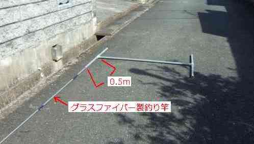
On the other hand, for the 21MHz antenna, I had been repeatedly cutting and adding elements for about eight years, and it was time to rebuild it. For this reason, I decided to rebuild everything except the fishing rod that supports the element.
I basically made it in exactly the same way as the one I made in April 1998, but since I was going to rebuild it, I thought I might as well incorporate some improvements, so I made a few changes. However, the boom part was changed from an FRP rod to a PVC pipe, and this part was not strong enough, so it bent a little.
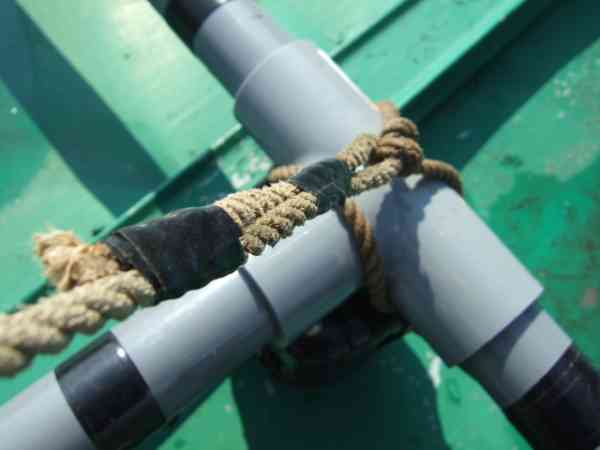
This was something I had anticipated from the start, and although it's a bit primitive, I plan to take the comic-like solution of hanging the boom from a string. Since it's only for short-term use, I don't think it will be a problem. Even when installed permanently, by hanging both ends of the PVC pipe boom with stainless steel wire, it has not broken even during typhoons. From this, it seems to be reasonably strong, so I think I will continue to use it.
This explanation also explains how to make a balun and a 75:50Ω conversion circuit. However, are they absolutely necessary? For example, if you don't add a balun, the beam pattern may become distorted, or unwanted radio wave radiation may occur midway through the coaxial cable. Also, if you don't add a 75:50Ω conversion circuit, even if you adjust it to the best, the minimum SWR will only be around 1.8. I think the antenna will still work without adding either of these.
If you think it's too much trouble to make these, try making it without a balun or 75:50Ω conversion circuit. As long as the antenna's resonant frequency doesn't deviate significantly (it will deviate if you change the element length arbitrarily or make the length carelessly), it should work fine. After you've confirmed that it works, you can add a balun or 75:50Ω conversion circuit later to further improve performance.
The fiberglass fishing rod used in the game used to be quite cheap and was intended for simple use by children, but recently fiberglass fishing rods have become less common. Instead, carbon fishing rods seem to be the norm. As you know, carbon fishing rods use conductive carbon material, so they cannot be used for the feeder line support part of the ZL Special. When purchasing, please make sure that the rod is made of fiberglass.
I also purchased a 3.6m fishing rod from Amazon, but when the material was listed as "glass," I assumed it was a fiberglass fishing rod, and the rod they sent me was actually a carbon fishing rod. The product photo on Amazon did not have the word "carbon" printed on it, but the rod I received clearly had "carbon" printed on the back. I'm thinking of repurposing this carbon fishing rod I mistakenly purchased for a V-dipole antenna (Banzai antenna).
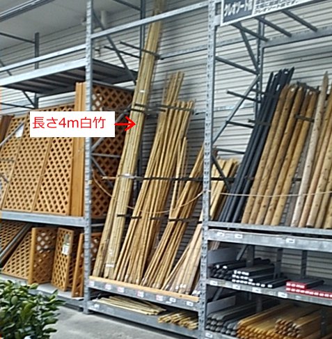
By the way, when I recently stopped by the home improvement store "Power Komeri," I found some materials that could be used as a replacement for a fiberglass fishing rod. They were selling 4m long bamboo rods for 268 yen (tax included). Since they're 4m long, if used to their full potential, I think I could make a ZL Special for 18MHz (each element is 3.89m long).
There are other lengths besides 4m, too, with 1.5m being sold for 95 yen, 2m for 138 yen, 2.5m for 158 yen, and 3m for 208 yen. This bamboo pole can be used not only for the ZL Special, but also to support the antenna elements of a V-dipole antenna. How about setting the bamboo poles in a V-shape on a plastic cutting board and adding IV wire to create a V-dipole (*Banzai antenna)?
If you want to cover the bamboo pole, which looks unsightly, shrink tubing for clotheslines is available for sale. An example of its use to protect the loading coil is given in the separate article "Building a 3.5/7MHz Angled Inverted-V Antenna." Please refer to that page if you are interested.
If you use this cover, once you've finished adjusting it, put the cover over the element's wires and the bamboo fishing rod, and it will also support the element, giving it a pretty smart finish. Bamboo rods are cheap, but covers cost about 700 yen each, so if you're going to use a cover, it might be cheaper to use a fiberglass fishing rod.
If you use this bamboo rod with the ZL Special, try tying a 4m rod to each side of a 50cm long piece of timber with wire, using a timber for the boom as well, and fastening the boom timber and the timber with the rod attached with a U-bolt. This bamboo rod has knots and is not as sleek as a fiberglass fishing rod. It will be a bit ungainly, but if you can't get your hands on a fiberglass fishing rod or want to make one as cheaply as possible, try checking out the gardening section at Power Komeri.
※各写真上をクリックすると拡大写真が見られます。
There were other products besides the 4m that
were sold under the name of Shiratake 4m |
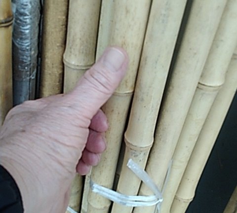
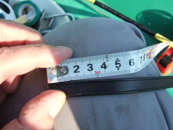
The diameter of my finger is about 20mm, so
the
diameter of the bamboo looks to be about 30mm |
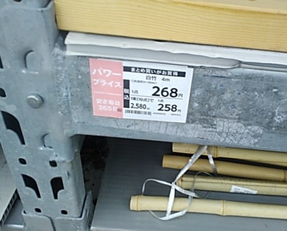
A 4m piece of white bamboo
was on sale for 268 yen |
 |
 |
 |
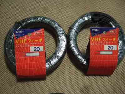
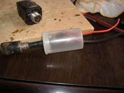
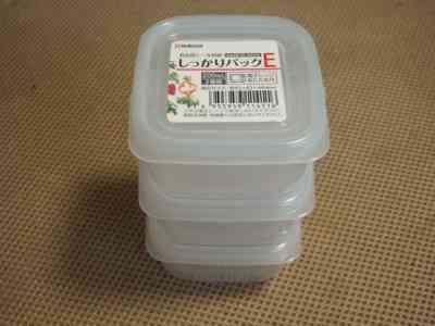
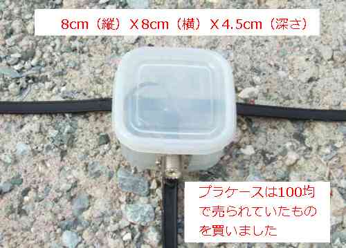
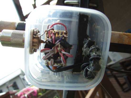
Below are photos of the process. I found a 20m roll of 300 ohm feeder wire that I had bought a long time ago, so I used that. In the past, I used a film case for the balun, but recently plastic cases of various sizes have been sold at 100 yen shops. I purchased one of these that seemed to be the best size.
I decided to use this plastic case after seeing it being used by JH6SNG (Yamamoto-san), who previously reported that "I made one for traveling and it was very FB," so I decided to do the same. The case I used was 8cm (length) x 8cm (width) x 4.5cm (depth). This time I only put a balun inside the plastic case, but there is enough space inside so I could have also stored a 75:50Ω conversion circuit.
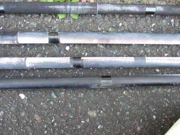
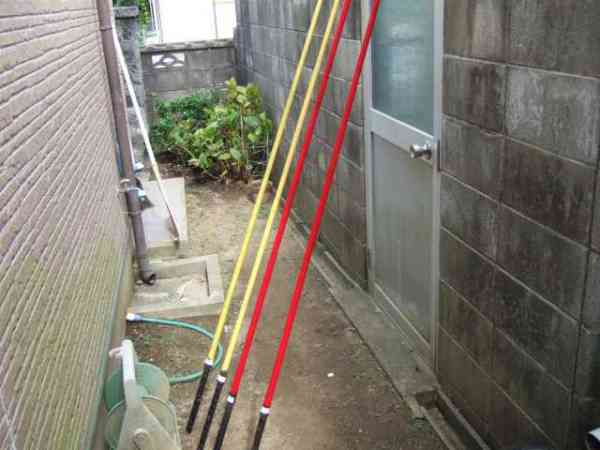
Previously, the PVC pipe into which the fishing rod was inserted was made 25cm long on one side, but this time it was doubled to 50cm. This was done because we thought the fishing rod had deteriorated after about eight years of use, and wanted to use as much of the thicker part of the rod as possible, which is thought to be stronger. Incidentally, the fishing rod is inserted halfway (25cm) into this 50cm long PVC pipe, so in effect the fishing rod has been extended by 25cm. This allowed us to cut off 25cm of the thin part at the tip of the fishing rod.
The element data for this project was created using the data introduced in "Redesign of the 2-element ZL Special Antenna Following Repairs (Final Report)." Specifically, it is the data in the table below.

The following photos show the work being done, including the processing work to store the power supply part inside a plastic case, the current state of the deteriorated fiberglass fishing rod, and the repainting process.
*Click on each photo to see an enlarged version.
I found a 20m roll of 300Ω feeder
wire that I had bought a while ago. |
In the old ZL Special, the balancer was
placed in the film case shown in the photo. |
I bought a set of three balun
storage cases from a 100 yen shop. |
 |
 |
 |
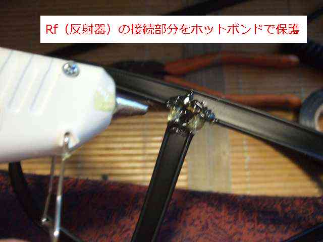
All terminals and connectionswere
coated with hot glue and then wrapped in tape |
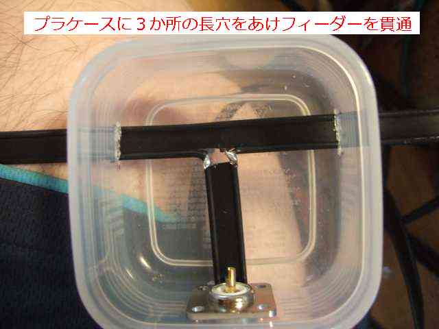
section is connected by drilling three holes in the
plastic case and
passing the feeder wire through them |
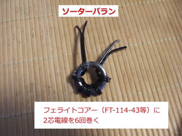
A simple structured Soter balun is used
FT-114-43 is wound with two-core wire six times |
 |
 |
 |
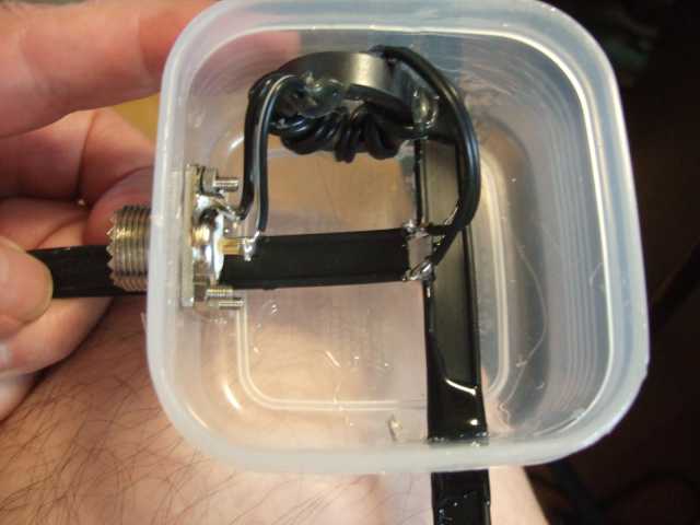
I placed the sorter balun I madebetween
the connector and the feeder line. |
The plastic case is finished with the lid on. Finally,
I wrapped it with vinyl tape to make it waterproof |
The completed element part
is attached
to the fishing rod and completed |
 |
 |
 |
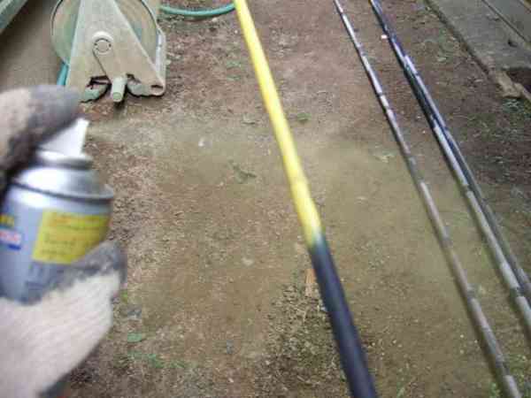
The paint on the fishing rod had peeled off in the
areas exposed to direct sunlight,
exposing the glass fibers |
I repainted the fishing rod
using some lacquer spray I had on hand. |
Insert the fishing rod into the H-shaped
PVC pipe to complete the support part |
 |
 |
 |
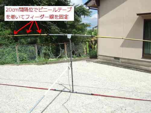
Fix the feeder wire to the fishing rod with vinyl tape
at intervals of about 20 cm and the work is complete |
The case containing the balun was completely protected by
wrapping it in vinyl tape due to weather resistance issues |
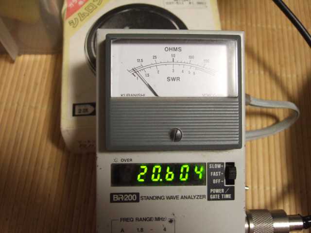
When I measured the resonant frequency,
it was low at 20.604MHz |
 |
 |
 |
I intended to make them with the same dimensions, but for some reason the resonant frequency seems to have dropped. The elements of the previous model have been cut and added over the past 8 years, so I have serious doubts as to whether the element lengths were ever exactly correct in the first place. Also, the core used in the balun was a rectangular core that was used in TV antennas, and was wound using the forced balun type shown in the left image below.
On the other hand, this time I used FT-114-43 for the core, but it was a cheap one that I found on an online auction for 180 yen each. Also, this time I used a super simple Souter balun (just wind two-core wire six times around the core) that doesn't require complicated wiring. This may have had a subtle effect. Incidentally, I reused the 75Ω:50Ω conversion circuit I made a long time ago, so I don't think it will have any effect.
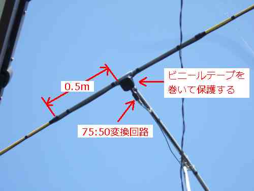
| About the 75Ω:50Ω conversion circuit |
The feed point impedance of the ZL Special Antenna is said to be approximately 90 ohms. If you feed it with a 50 ohm coaxial cable, the SWR will be 1.8 (90 ohms/50 ohms = 1.8). Even in this state, the SWR is still below 2.0, so I think it should still be usable.
For high-power stations, a slight power reduction is probably not a problem, but for a QRP station like me, I honestly want to keep the SWR as low as possible. If you want to achieve an SWR of exactly 1.0, you will need to use an antenna coupler or something similar to achieve matching.
The 75Ω:50Ω conversion circuit introduced below provides a simple, fixed-ratio impedance conversion. It converts impedance to 1/1.5 (75/50=1.5). When used with a ZL Special Antenna, it can convert a 90Ω impedance to 60Ω (90Ω/1.5=60Ω). Without this conversion circuit, the minimum SWR is 1.8, but adding it reduces the SWR to 1.2 (60/50=1.2).
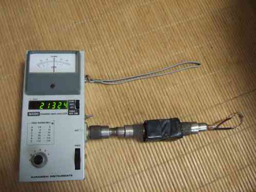
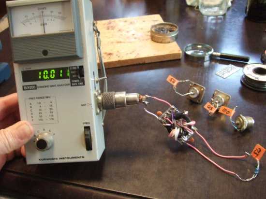
I have previously taken photographs of this conversion effect, which I will introduce below. The first photo shows that when measuring impedance using a 75Ω resistor (two 150Ω resistors in parallel) as a dummy load, the reading was 80Ω. It should normally read 75Ω, but since the measurement was performed with the frequency set to around 21MHz, the resistor used did not appear to have very good high-frequency characteristics, so it read 80Ω. If I had measured again with a frequency set to 10MHz or lower, it would probably have displayed 75Ω. Incidentally, the DC resistance value I checked with a tester beforehand was 75Ω.
Next, I inserted a 75Ω:50Ω conversion circuit and measured the impedance, which was displayed as 50Ω. It appears that the 1/1.5 conversion has become a 1/1.6 conversion. I was hoping for something with a slightly larger conversion ratio, so this is exactly what I was hoping for.
*Click on each photo to see an enlarged version.
Measuring impedance with
a 75 Ω resistor as a load |
Enlarged view of the
photo on the leftIt says 80Ω |
Measuring impedance with
a conversion circuit inserted |
Enlarge the photo on the left.
It says 50Ω |
 |
 |
 |
 |
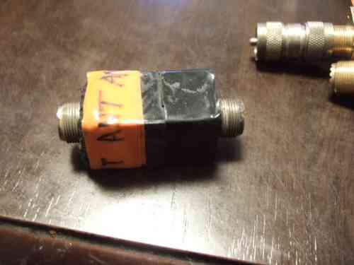
In this renewal work, we reused the existing 75:50Ω conversion circuit as mentioned above. In the past, we made a conversion circuit by cutting out a bare double-sided printed circuit board to create a rectangular case, storing the conversion circuit inside, and attaching female coaxial cable connectors to both ends of the case to create a sealed type.
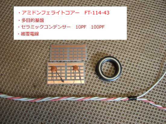
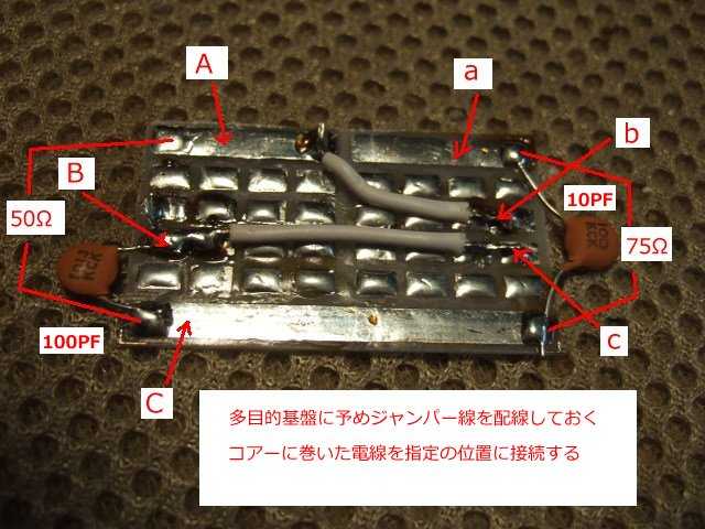
So, although I didn't make anything new this time, for reference I'll introduce here again the 75Ω:50Ω conversion circuit I made in the 50MHZ 2EL ZL Special section. The "multipurpose board" mentioned in the text is just a name I came up with, and it was listed on an online auction site. It's listed for a very low price. It seems like it could be used in a variety of cases other than the one mentioned here, so I recommend taking this opportunity to purchase one.
The 10PF and 100PF ceramic capacitors used in the circuit are subject to high voltages depending on the output. For this reason, you need to use capacitors with a voltage rating appropriate to the output being used. If you are purchasing new capacitors, it is best to purchase ones with as high a voltage rating as possible.
OM Kikuchi, JA1HWO, has published a tool to calculate the voltage across a capacitor. When you enter the output power, the resulting voltage across the capacitor is calculated. If the SWR is high, the impedance will be high and the output voltage will be high. OM Kikuchi states that it is best to plan for an SWR of around 3. If you want to know the voltage across the capacitor, click the link below, enter the power you are using in the data input box, and check the voltage across the capacitor
 Website for calculating the voltage across a capacitor *This is introduced on OM Kikuchi's website.
*Click on each photo to see an enlarged version.
Wire, core, and two multipurpose
ceramic capacitors |
75Ω:50Ω conversion circuit |
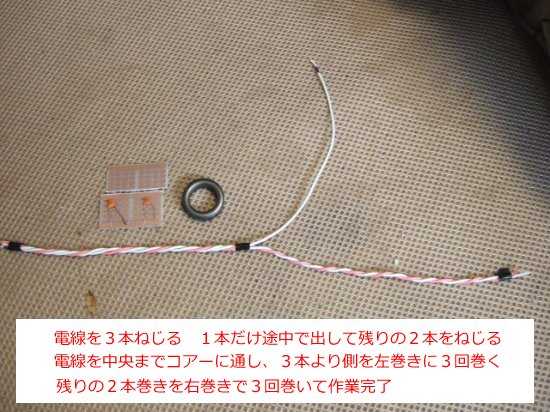
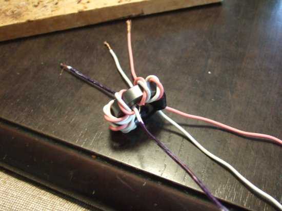
Wind the wire around the
ferrite coreas specified |
Ferrite core with
wire wound around it |
 |
 |
 |
 |
Attach jumper wires and capacitors
to the multipurpose board |
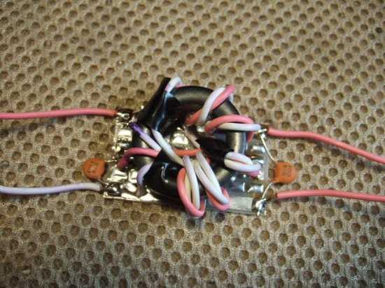
Attach the wire wound around
the core to the board |
During operation check
with the analyzer |
Store the conversion circuit in
the box and the work is complete |
 |
 |
 |
 |
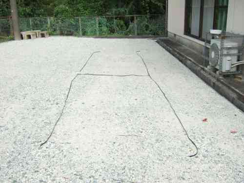
By the way, the ZL Special Antenna uses a 300 ohm feeder wire. As you know, this feeder wire has a folded structure. Folded dipole antennas using this feeder wire are said to have a wide resonant band.
For this reason, this ZL Special antenna, which uses the same 300 ohm feeder wire for its element, also seems to have a wide resonant band. When I measured the SWR before modification, it was a maximum of about 1.3 within the band. There doesn't seem to be any particular problem if I use it as is, but I will be lowering the antenna later to suspend the boom with a string, so I plan to shorten the element at the same time.
| Element trimming is complete |
The reason why the resonant frequency dropped so much is unknown, but for the time being, we considered shortening the feeder again to raise the resonant frequency. Changing the calculated frequency from 20.998 MHz to 21.200 MHz results in the element shortening ratio = 20.998/21.200 = 0.99. Multiplying this shortening ratio by Ra of 6.50 m gives us 6.44 m (6.55 x 0.99 = 6.435). Multiplying RF of 6.64 m by the shortening ratio of 0.99 gives us 6.57 m (6.64 x 0.99 = 6.573).
At this point, we should actually calculate the distance S between Ra and Rf to 1.59m and shorten it, but this is not possible due to the structure. When we calculated the length of S using MMANA, we found that even if the length was changed slightly, there was no significant change in the front gain or F/B ratio, so we left the length of S at 1.59m. The above is the result of our investigation. Specifically, we will shorten Ra from 6.50m to 6.44m, and Rf from 6.64m to 6.57m.
With the above modifications, the calculated resonant frequency is 21.178MHz. I tested it to see if it would actually match the calculation. The result was a resonant frequency of 21.098MHz, as shown in the table below. The difference between the MMANA calculation result and the actual measured resonant frequency was only 80KHz, so I was able to achieve almost the desired modification result.

The calculation results for the above element data are linked below. If you are interested, right-click on the file below and select "Save link as" to download the MAA file. If you open the downloaded MAA file in the MMANA software, you can see the detailed calculation results for the antenna.
Download 21MHZ.MAA
MMANA software (MMANA for Windows Ver. 1.77) download site
JE3HHT Mori OM's homepage
300Ω feeder wire sales site Oyaide Electric homepage
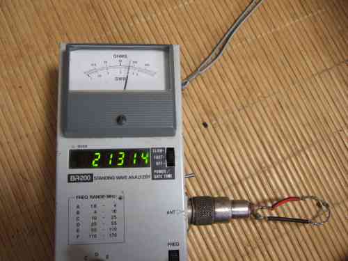
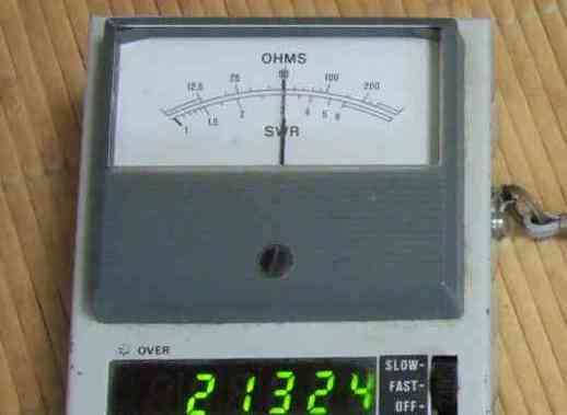
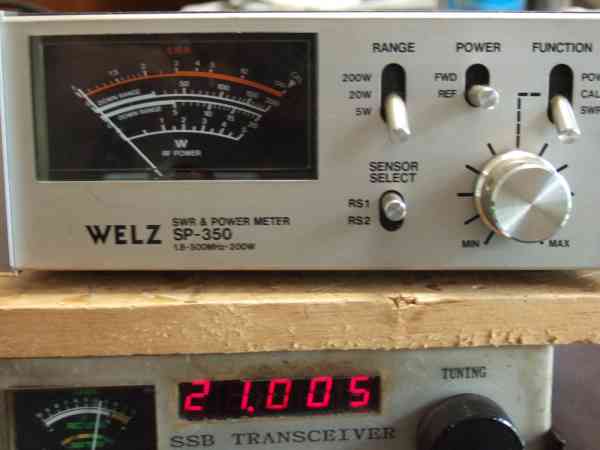
After the modification, I actually applied power and measured the SWR, and the result was amazing: almost no reflection was observed within the band. The SWR measurement value can be seen in the photo below. I was surprised by the result and thought, "Is that really true?"
However, the measured power was only 3W, so I think that may be a factor. If the power were 100W, I think there is a possibility that more reflected waves would be generated. However, it seems to be absorbing the waves well, so it should be performing reasonably well.
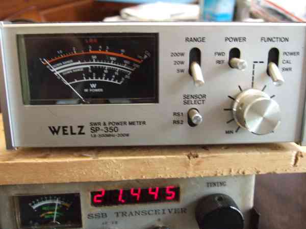
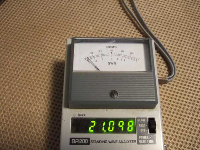
The SWR value was so low that after measuring the highest frequency of 21.445 MHz, I changed the SWR meter to one from a different manufacturer, but the result was the same wide bandwidth, with the SWR value remaining low.
Also, since the measurement was not taken directly under the antenna, but via a coaxial cable about 15m long, it is possible that the reflected wave was carried by the coaxial cable and fell into the valley of the reflection, causing the apparent SWR to drop. To confirm this, we added a coaxial cable about 4m long and measured the SWR again, but the SWR value did not change. This means that it appears to be absorbing waves well after all. There is no limit to what can be doubted, so we will simply assume that it was set up well.
*Click on each photo to see an enlarged version.
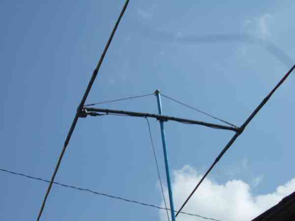
I tried to hang it with a rope I had,
butthe rope stretched and it didn't work |
For the time being, it was hung with nylon rope, but
now it is hung with stainless steel wire. |
The Ra element was shortened by 3cm on one side
, and the Rf element was shortened by 3.5cm on one side. |
 |
 |
 |
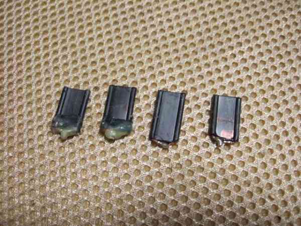
Cut off remains The remains are about 1cm short
because each terminal needs to be shorted |
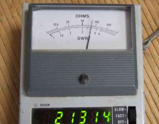
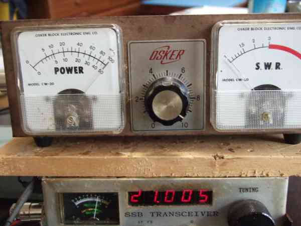
While measuring at 21.005MHz, the reflected
wave only fluctuates by about one needle width. |
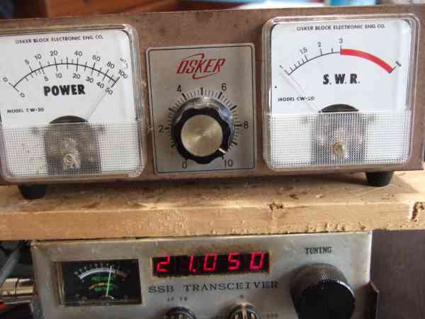
While measuring at 21.050MHz, the reflected
wave only fluctuates by about one needle width. |
 |
 |
 |
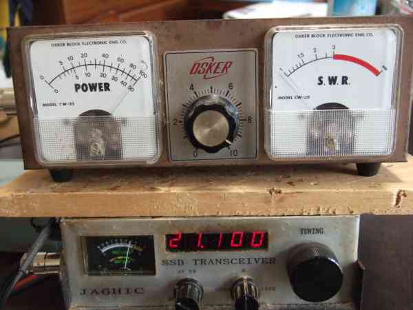
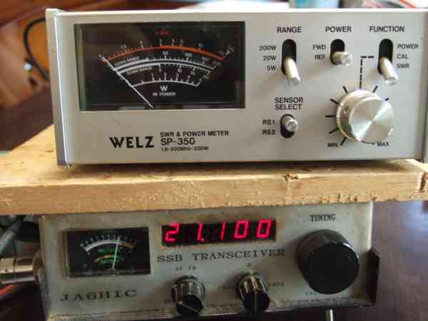
While measuring at 21.100MHz, the reflected
wave only fluctuates by about one needle width. |
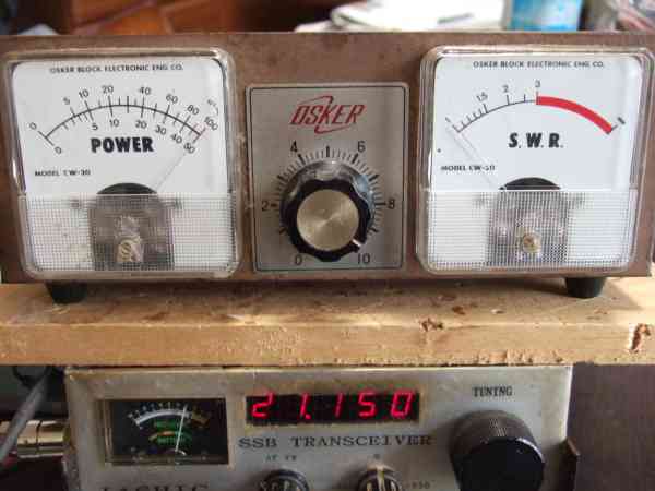
While measuring at 21.150MHz, the reflected
wave only fluctuates by about one needle width. |
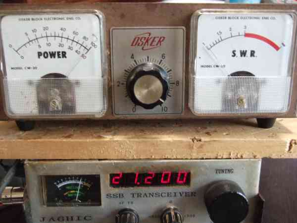
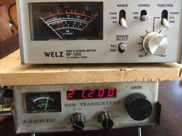
While measuring at 21.200MHz, the reflected
wave only fluctuates by about one needle width. |
 |
 |
 |
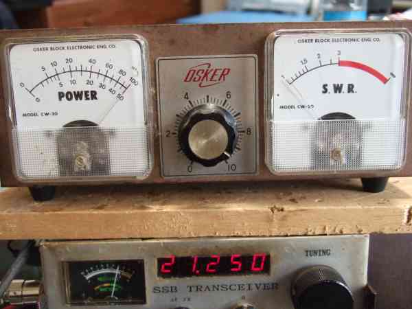
While measuring at 21.250MHz, the reflected
wave only fluctuates by about one needle width. |
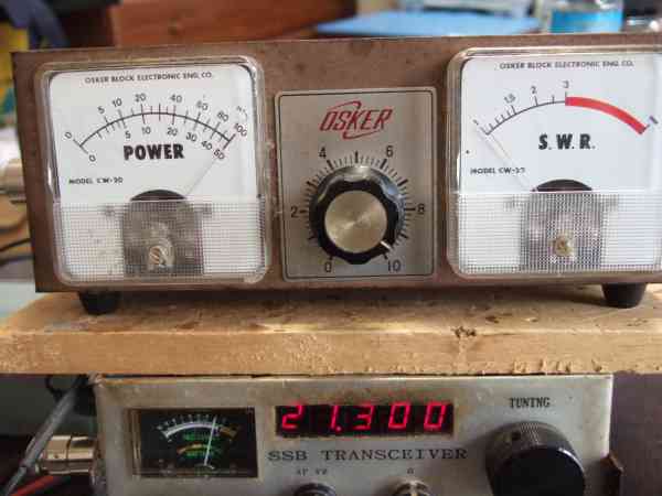
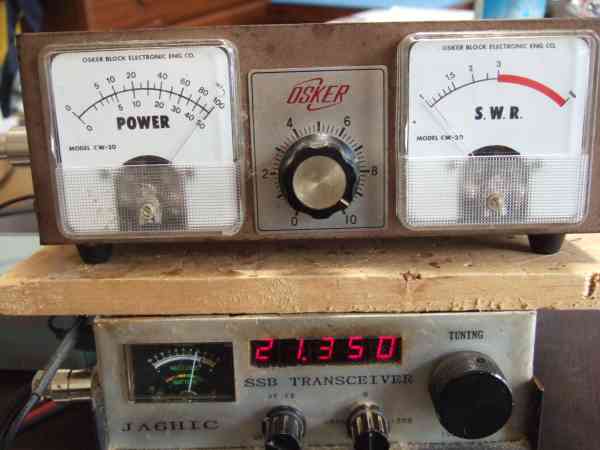
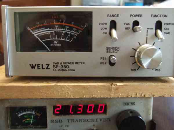
While measuring at 21.300MHz, SWR=1.01,
a small reflected wave finally appeared |
While measuring at 21.350MHz, SWR=1.02,
the reflected wave increased by the width of a needle compared to before. |
 |
 |
 |
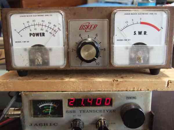
While measuring at 21.400MHz, SWR=1.03
reflected
waves increased slightly from the previous measurement. |
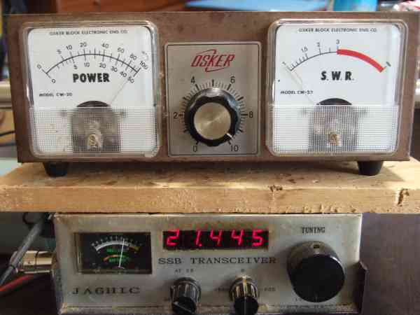
Measuring at 21.445MHz, SWR=1.05 This
is the maximum value measured this time. |
Change the measuring instrument and
complete
the setting at full scale during calibration |
 |
 |
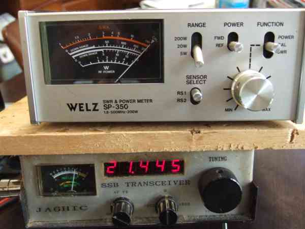 |
| SWR=1.05 (measured at 21.445MHz same as other manufacturers' results |
While measuring at 21.300MHz, the reflected wave
only fluctuates by about one needle width. |
While measuring at 21.200MHz, the reflected wave
only fluctuates by about one needle |
 |
 |
 |
While measuring at 21.100MHz, the reflected wave
only fluctuates by about one needle |
While measuring at 21.005MHz
the reflected wave
only fluctuates by about one needle |
The measured resonant frequency was 21.098MHz
which was 80KHz different from the calculated value. |
 |
 |
 |
This 21MHz 2-element ZL special antenna encountered many problems during construction, but I finally achieved a satisfactory result. I apologize to those who built it using data from an incomplete modification, as I had to change the element data many times, causing a lot of trouble. However, I managed to complete it after much hard work.
However, this struggle is also the joy of building your own antenna, and when you finally get a satisfactory result, you'll be glad that all the hard work was worth it. Why not try experiencing the joy of building your own antenna? In that sense, I encourage you to try building your own ZL special antenna.
| Remeasurement with NanoVNA-H4
|
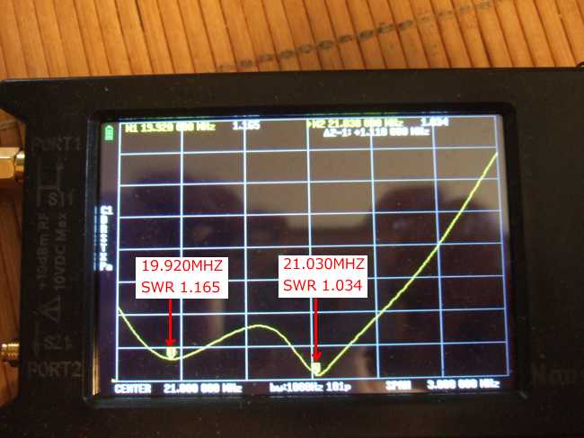
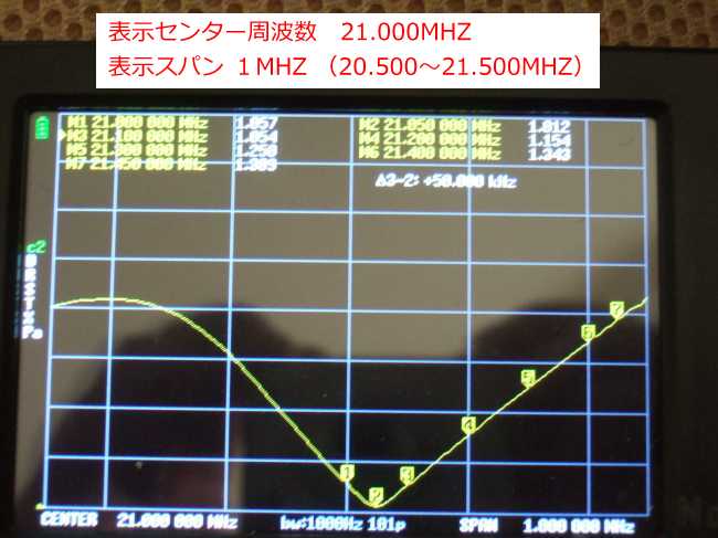
While I was building a 50MHz 3-element antenna, the SWR reading was so low that I purchased a new antenna network analyzer, the NanoVNA-H4, and measured it. The results showed that the NanoVNA reading was about 0.2 higher than the SWR reading measured with the SWR meter. The SWR of this 21MHz ZL Special was also so low that I measured it with the NanoVNA I had purchased just to be sure, and the results were as shown in the photo below.
*Click on each photo to see an enlarged version.
There were dips at
19.920MHz and 21.030MHz |
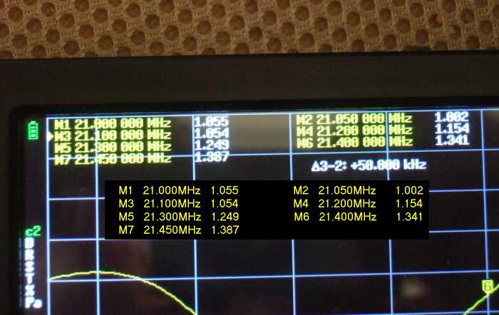
Markers are set every 100KHz from
21,000MHz to display the SWR value |
Frequency and SWR value for each
markerUp to eight markers can be set |
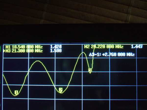
I measured it on a rainy day
and there were three dips??? |
 |
 |
 |
 |
Seven measurement point markers were set (up to eight can be set) at 100 kHz intervals starting from 21.000 MHz. The frequencies and SWR values of the seven markers are listed at the top of the screen. Marker 1 is at 21.000 MHz, with an SWR value of 1.055. Marker 2 is the resonant frequency at the lowest SWR point, 21.050 MHz. The SWR value at that point is 1.002. Markers are then displayed every 100 kHz, and marker 7 is at the band edge, 21.450 MHz, with an SWR value of 1.387.
As expected, the SWR value was about 0.2 to 0.3 higher than the actual SWR value measured with an SWR meter. I think the NanoVNA measurement probably displayed a more accurate SWR value. However, the dip point (resonance point) of 21.050 MHz for Marker 2 was unusually close to the dip point of 21.098 MHz measured with the Kuranishi analyzer BR-200. Also, when measuring on a rainy day when the feeder wire got wet, the overall resonant frequency dropped, and strangely, one more dip point appeared, making it three. Why? It's a mysterious phenomenon.
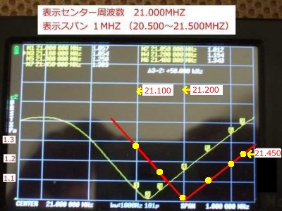
By looking at the SWR curve directly in this way, we can see that if we raise the resonant frequency by another 100 kHz to 21.200 MHz, the SWR curve will shift parallel to the right, and even at the band edge of 21.450 MHz, the SWR will be around 1.2. By making good use of the NanoVNA in this way, we believe we can get even closer to an ideal antenna.
Even so, it's a strange phenomenon that the SWR measured by the SWR meter is so low. Is it because I'm measuring at a low power of about 3W? In any case, the SWR is within 1.4 within the band, so that's fine.
While we're on the subject, I'd like to introduce the antenna analyzer NanoVNA that I used for this measurement. It seems to be listed on online auction sites from time to time, but I purchased it from Amazon, which I'll link to below.
NanoVNA-H4 Amazon sales site *The price went up for a while, but it seems to have settled down a bit now.
The operation of this measuring instrument is explained in detail in the separate section "Antenna Network Analyzer NanoVNA." It can be used for various purposes other than measuring the SWR of antennas, so please take a look if you are interested.
| How powerful is the 2EL ZL Special? |
We are currently working on upgrading the ZL Special for 21MHz to 3EL, but due to the unusually hot weather this year, the work has been suspended. Therefore, we are currently operating with the existing 2EL configuration. Taking advantage of the time that work was suspended, we investigated the capabilities (performance) of the "renewed 2EL ZL Special antenna" currently in use.
Specifically, I rotated the antenna while receiving the signals of the stations that I was actually in contact with that I could hear as direct waves (terrestrial waves), and checked the signal strength of each signal at the front, side, and back with an S-meter. Since the antenna is 2EL, I didn't think it would be much of a beam antenna.
However, it worked perfectly as a beam antenna. When I pointed the antenna towards the front, the S meter swung wildly, and I could see that the signal was disappearing on the sides. Phase-shifted power-feed type antennas are said to have good side cutoff, and this characteristic was beautifully displayed. Also, unlike my old builds where it was hard to tell which was the front, the front and back were clearly distinguishable.
To check the front gain, we switched between the dipole antenna and the ZL Special to check the signal strength, and there was a clear difference. In the case of a particularly weak signal, switching from the ZL Special to the dipole antenna made it completely inaudible, but switching back to the ZL Special made the audio discernible. Even with a relatively strong signal, switching the antenna to the dipole antenna resulted in audio with noise, but switching back to the ZL Special eliminated the noise and the audio became clear, making for a clear difference.
On another occasion, I have had the opportunity to switch between ZL Special and dipole antennas during actual contact and ask the stations to send me their signal reports. Most of the stations responded that the ZL Special gave them a signal report that was about two levels higher.
The dipole antenna is stretched in a direction that produces a directional pattern (figure-eight characteristic) for domestic use. The dipole antenna is stretched from the top of a 12m concrete pillar, making it higher than the ZL Special (6m above ground). The ZL Special was rotated to a position where each signal was maximized for comparison. The Australian (VK) station is located due south, so the dipole antenna's orientation may be slightly off.
So, the above is a written description of my observations, but I felt that this would not be enough to judge the extent of the effect, so I took a video of the change in signal strength when I rotated the antenna, and when I switched between the ZL Special and dipole antennas. Since I took the time to film it, I have already uploaded it to YouTube. Seeing is believing, so you may think that the HIC station's explanation is an exaggeration, or that it is exactly as the HIC station explained it. Please take a look at the YouTube link below.
Link to the ZL Special performance (YouTube)
What are your impressions after watching this? Changing the subject here, the light bulb in the rotator controller burned out, so a non-standard light bulb was installed. This caused the controller's lighting to be abnormally bright, and the video camera reduced the brightness during filming, making it difficult to see the S meter on the transceiver.
By the way, in QRP operation, it is taboo to use an antenna with a high SWR, because the effective power drops when the SWR value is high, in addition to the already low power. For this reason, I pay particular attention to the SWR value and adjust the element length in centimeters until the antenna is complete. Personally, I think that these characteristics are quite good for 2EL, but what do you all think?
 Return to Home Page