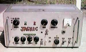
The transmitter below is an A3 (AM) transmitter for 3.5 to 50 MHz that was made when the station first opened in 1967. At the time, it was common for people to make their own radio equipment, and if you said "I made my own radio" when making a contact, people would think, "That's a given, what a strange thing to say."
I remember it took about a month to complete, using all the tools I had on hand, such as a hand drill (I didn't have an electric drill at the time), a reamer, and a chassis punch, and getting blisters on my hands.
At the same time as making the transmitter, I also made a single-conversion type receiver, but I gave it to a student at a certain technical high school, so I no longer have it. I just couldn't bring myself to throw away this transmitter, so I left it in my junk warehouse.
The gray square case on top of the transmitter in the photo below is the VFO for this transmitter. For reference, I have placed my No. 5 on the upper right of the transmitter. Looking at it like this, you can really feel the passage of time.
People today may wonder how someone could build a transmitter when starting a station, but in the past, amateur radio operators had some experience in building their own transmitters, and building their own radios was an extension of that experience. For example, I built a Class 5 super radio with an ST tube as part of a club activity in junior high school.
A junior high school student with no experience building radios tried to assemble it while looking at the actual wiring diagram, but of course it didn't work at all. After that, he tried again to build a radio for first-year high school students, which doesn't require complicated adjustments, and this time he completed it beautifully. I still remember the excitement when I heard the radio sound coming from the speakers. In fact, this successful experience became addictive, and he ended up embarking on a path of DIY that he shouldn't have taken.
After that, I continued to make my own radios and audio amplifiers. If you think about it, a radio is a receiver, so the only difference is whether the receiving frequency is the BC band or the amateur radio band, and if you can make a radio, you can also make an amateur radio receiver.
As for the transmitter, the audio amplifier circuit is exactly the same as the audio amplifier circuit, except that the output transformer of the audio amplifier is replaced with a modulation transformer.As for the high-frequency transmission circuit, we had already experimented with BC band wireless microphones, so the only difference is the power it can handle.
Considering this, it's not surprising that amateur radio equipment could be made by hand before starting a station. In fact, in my case, it wasn't particularly difficult, and I remember completing it fairly easily. Above all, there were many genuine amateur radio operators around me who had the technical ability to make their own radio equipment. When I listened to the content of the contacts, it wasn't like today's "Signal Report 5/9, card is JARL, goodbye," but rather there was a lively exchange of technical information about radio. Perhaps the reason I was able to make my own transmitter, as shown in the photo below, was because of the backdrop of the good old days, when it was common to make your own radio equipment.
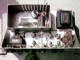
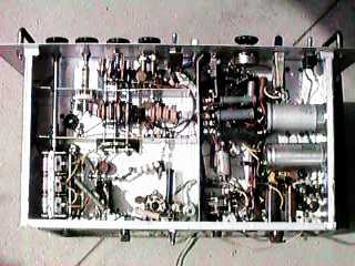
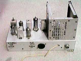
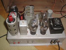
The photo on the bottom left is a top view of the transmitter. The square aluminum case in the upper left contains the tank coil and final stage vacuum tube 6146. The transformer in the lower left is a choke coil for the power supply smoothing circuit. Below the vacuum tubes (two vertically) directly next to it is the 6CL6 oscillator tube when using a crystal, which acts as a buffer amplifier when using a VFO. The vacuum tube above is the 6CL6 driver tube. (Note: The 6CL6 is a television video amplifier tube with similar performance to the 12BY7.)
The large black transformer on the top right is the power transformer. Below it is the modulation transformer, and the four vacuum tubes to the left of that are for audio amplification: a 6AU6, a 12AX7, and two 7189A (6BQ5) tubes. I don't remember the details, but I purchased a coil kit (I think it was Trio?), and used parts I had on hand for the power transformer and choke coils for an audio amplifier. I purchased the modulation transformer and vacuum tubes I didn't have on hand from Ozawa Denki Shokai in Akihabara (I was a regular customer of this store's mail order service).
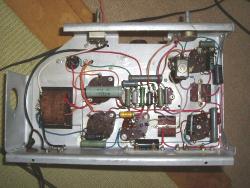
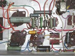
The photo on the right below shows the parts installed inside the chassis. Shield plates are attached where necessary. It may sound strange to say it myself, but I feel like I'm echoing the famous words of female marathon runner Arimori, "I want to praise myself." I'm only just realizing that I had a lot of horsepower back then.
※Duplicate of the homemade transmitter construction design document at the time of application for station opening in 1967


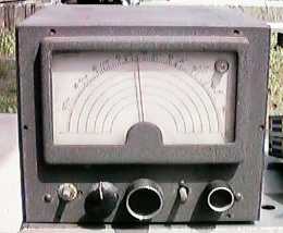
The photo below shows the VFO for the transmitter. Naturally, the LC is placed inside the LC box as per the standard. This VFO emits in the 3.5MHz range and was used for transmitting from 3.5MHz to 28MHz.
I didn't use this VFO for 50MHz band operation, but I remember using a crystal in the 8MHz range for spot operation. Also, the entire metal case was made by Settsu Metals for VFO use.
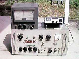
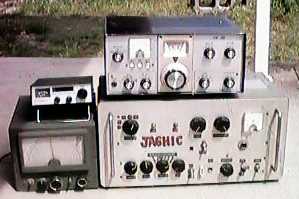
The photo below recreates the operational state at the time. The VFO is in the lower left, the transmitter is next to it, and the receiver (Yaesu FR-50) is placed on top of the transmitter. It was truly a struggle to assemble all of this equipment to finally be able to make contact.
Just for fun, I placed No. 5 on top of the VFO. Although the output is different, such a small setup can transmit SSB radio waves, and there is no QRH, so the world has come a long way. However, when I line them up like this, the old set somehow feels heavier (and I'm not talking about weight, of course), and I feel that this is really radio equipment. Is this just the mindset of old-fashioned amateur radio operators?!
For a few years after starting the station (about two years?), I communicated on AM radio waves, but then I started to hear a buzzing sound every now and then in the radio waves that had previously been dominated by A3 (AM waves). I had already seen articles in magazines and other sources that told me that this was SSB waves, so I could easily guess that it was. However, my high school and junior high school year 1 receiver had difficulty demodulating the signal, and I had to frequently adjust the RF gain to get it to work.
Around that time, Yaesu Musen released the FR-50 receiver, designed for SSB operation. So, I used my meager bonus money to purchase this receiver. This receiver could be paired with the FL-50 transmitter for transceiver operation. I wanted to try SSB operation, but I didn't have enough money to buy an SSB transmitter. Also, as an amateur radio operator, I was a little reluctant (or maybe just sour grapes?) to use manufacturer-made transmitters and receivers.
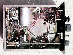
So, I decided to put my own skills aside and boldly try to build an SSB transmitter that could transceive with the FR-50. The photo below shows the SSB generator and transverter I built at that time.


To cut straight to the chase, this reckless plan was a complete failure. At the time, all we had were testers and little more than a few other measuring instruments, and we didn't even have a frequency counter to align the carrier point.In terms of the circuit, the plan was to generate an SSB signal using a 455 kHz SSB generator, mix this with the first local oscillator (fixed at around 16 MHz) and second local oscillator (variable at around 5 MHz) extracted from the receiver, and create a 21 MHz SSB wave.
There was nothing wrong with the circuit configuration, but upon closer examination, I now wonder whether the transistors used in the SSB generator were germanium type transistors that came with a transistor radio, and whether they were able to provide a decent oscillation level. Furthermore, since the generator receives and uses two local oscillator signals from the receiver, I suspect there was also a problem with this level (if the receiver's local oscillator were to be used as is, a buffer amplifier would be required).
Although I was able to confirm the 5MHz SSB signal wave with a transistor radio (I could hear a buzzing sound), I was unable to extract the desired 21MHz SSB signal as power. After that, I had to put the project on hold due to work-related transfers and other reasons, and in the end, this project remains incomplete to this day.
This happened about two years ago, but my son (a university student) lives in an apartment in Yamaguchi Prefecture, so I had the opportunity to take a look at a recycle shop in Yamaguchi City (which also sells antiques).
I wasn't particularly interested in antiques, but my eye was caught by several five-tube ST super radios that seemed to be from the 1940s. Items using MT tubes are not that rare, but the fact that they used ST tubes gave me a strangely nostalgic feeling that piqued my interest.
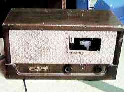
In the end, I brought home a total of three ST tube radios from this recycling shop, and the radio I'm introducing here is one of them, and it looks like the one below.
I was shocked when I took them home and looked inside the chassis. Of the three I brought home, only one had no resistors, capacitors, or other components inside the chassis. The inside of the chassis just had a bare copper earth line wired in a straight line!! Come to think of it, there was indeed a label saying "Sold as is." The antiques dealer knows what he's doing. "Sold as is?" I thought to myself, there's no way he's going to repair it and then give it to me.
So, for the first time in over 30 years since I was in the second year of junior high school, I decided to assemble a five-tube ST super radio. The vacuum tubes used are ST tubes 6WC5, 6D6, 6ZDH3A, 6ZP1, and 80BK . It's a classic lineup, and I'm sure some old-school students will say, "Wow, those are nostalgic names.
There are no records of the circuit diagram used for assembly, but it is believed that it was probably assembled using a circuit similar to the one below. The circuit diagram below is a reprint of one that appeared in the December 1950 issue of a magazine called Radio Technology. The circuit is thought to be a standard circuit for a Class 5 ST tube super.
I tried to assemble it, but it wasn't that easy when it came to vacuum tube parts. Fortunately, I had some leftover parts from a vacuum tube audio amplifier, so I removed the capacitors and resistors from that and used them. In particular, I managed to make do with capacitors (50V rated) that are currently used in transistor circuits, especially in areas where high voltage is not applied, such as the grid circuit.
The most difficult problem was that I didn't have a local oscillator coil and padding capacitor. I looked everywhere but couldn't find them, so I finally asked my fellow builder, Mr. Hanamura (JA6DWO), to look in the treasure chest (junk box) in his "locked room" and we finally found them. Once I finally got all the parts together, I reminisced about the old days and assembled a vacuum tube radio for the first time in a long while. The inside of the completed radio chassis looked like the photo below. I used lug boards to group the capacitors and resistors together, so it turned out to be a fairly neat and tidy finish (maybe I'm just bragging?).
At first glance, it seemed like bad luck that there were no parts inside the chassis, but after assembly and adjustment, I was able to hear the broadcast signals so well that I wondered, "Was the sensitivity of a five-tube super radio really that good?" When I think about it, the output from the broadcast station has certainly increased compared to the past. Although I only used a 2-meter vinyl cord for the antenna, I was able to receive NHK and various commercial stations with great power.
"Turning misfortune into blessing," I was able to try again to build a five-tube super radio that I hadn't completed in my second year of junior high school. Although I struggled to procure parts, I was able to assemble and play with a five-tube ST super radio for the first time in a long time, so I'm very grateful to the antiques dealer. The photo below shows the completed assembly of the five-tube ST super radio.
I found a nostalgic wiring diagram!
While I was searching for a circuit diagram to assemble a five-tube ST super radio, I found a circuit diagram for a high school radio that used ST tubes. Wow, that brings back memories. Come to think of it, when I was in junior high school, I used to build things while looking at actual wiring diagrams.
The actual wiring diagram 2 below has the publication date of the printed material. It says April 25, 1956, Fuji Manufacturing (STAR). That makes it a printed material from 42 years ago! Even so, the actual wiring diagram is really well drawn. I think it was drawn by a professional artist, and they must have drawn it faithfully while looking at the actual machine. I'm sure OM will say it brings back memories. Looking at it might take you back in time to your younger days.
 Return to the homepage