No. 3 Machine
(Last UP Date December 19, 2001)
This rig was made for handheld operation. It uses the case, volume controls, speaker, meter, etc. of an old manufacturer's handheld transceiver (Trio TR-3200), and replaces all the internal circuit boards to enable 21MHz SSB operation.
When this was first made, Toshiba's TA7320 was used for the modulation/demodulation circuit, but since it only provided about 30dB of carrier suppression, the modulation/demodulation IC has now been replaced with a Signetex NE612AN to improve performance.
Front operation panel layout (dials and volume control layout)
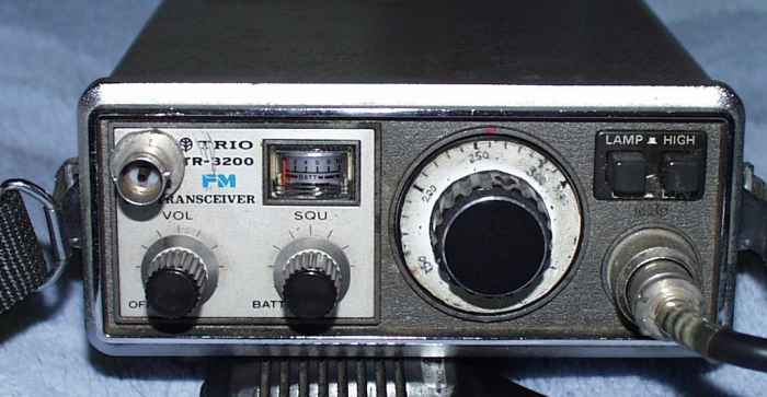
The photo above shows the handheld radio from the front. The knob on the bottom left is for adjusting the volume, and the knob to the right of that is directly connected to a 3PF variable capacitor, allowing for fine tuning of the frequency.
The main frequency adjustment is done with the large dial located slightly right of the center. This dial is directly connected to a 30pF variable capacitor, and the frequency can be changed by turning this dial. The variable frequency range is about 150 kHz, from 21.150 MHz to 21.313 MHz, and the frequency is changed using the VXO method.
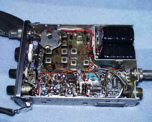
Top surface board layout (explanation of the boards arranged on the top surface)
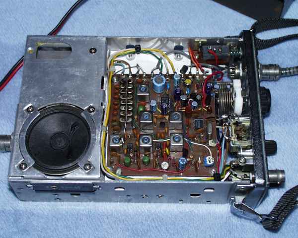
The above photo shows the SSB generator board side with the outer case removed. The filter, which is the heart of the SSB transmitter, is a ladder-type filter, which I also made myself.The homemade filter is made using eight junk 9.216MHz crystals. The eight crystals lined up on the top right of the speaker are the filter part.
SSB generator circuit
As mentioned above, the SSB generator circuit uses the NE612AN from Signetex for modulation and demodulation. This IC provides sufficient carrier suppression without the need for a carrier balance circuit.
This IC has a built-in carrier oscillator circuit, which automatically sets the injection level, etc., and although the input frequency can be up to 500 MHz, it is used at around 9 MHz, so it seems that the carrier balance is good from this point onwards.
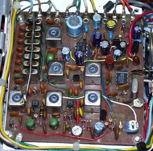
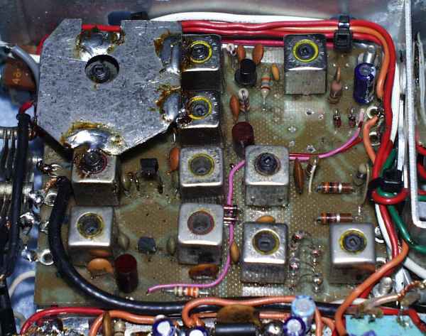
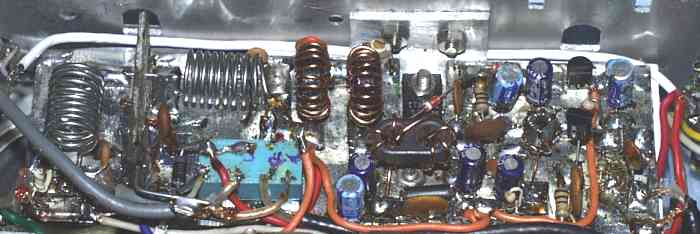
Bottom board layout (explanation of the boards located on the bottom)
The photo above shows the underside, where the transverter and final stage power amplifier are located.
The upper left part of the photo is the transverter, the black object to the right is the battery (600mAh Cadmium x 10), and the thin part at the bottom is the final stage power amplifier circuit. The final stage transistor is a 2SC1957, and the maximum output is 3W.
Transverter Circuit
This transverter circuit converts the 9.216MHz SSB signal from the SSB generator to the desired 21MHz. The mixer uses a diode mixer circuit with four 1N60 diodes.
The transmitter and receiver amplifiers are both made of 2SK241. The local oscillator circuit uses a 10.18MHz junk crystal as a VXO oscillator, and the tripled output is used as the local oscillator.
Final stage power amplifier circuit
When the final stage power amplifier was first produced, it was made with a wide type amplifier using 2SC2166. This circuit sometimes caused self-power issues when using a whip antenna, and its operation was unstable. Therefore, it has now been rebuilt with the same circuit as No. 5, which operates more stably.
Wiring of each circuit board
This unit, No. 3, uses a VXO circuit for the local oscillator, making the circuitry very simple. It consists of only three circuit boards: an SSB generator board, a transverter board, and a final stage power amplifier board.
The wiring method for the three circuit boards is as shown in the overall wiring diagram below.
Impressions after using it
 |
|
It seems that VXO is the standard for local oscillators in home-built radios, but considering the variable frequency range and QRH issues, a PLL local oscillator is the winner. Since this No. 3 radio is intended for portable operation, I have chosen to use a VXO in the local oscillator circuit to reduce current consumption, leaving aside the QRH issues.
There seems to be a VXO circuit that uses two of the same crystals in parallel to make the variable frequency range as wide as possible, but in any case, it is impossible to expect performance on a par with that of a PLL, so I decided to forgo any clever gimmicks and simply use a normal circuit.
Ignoring the QRH issue, I have made it possible to tune the frequency by about 150 KHz, so fine tuning of the frequency is necessary for long QSOs. For this reason, I ask at the beginning of the QSO that there will be a QRH.
Since there is no frequency fluctuation in a homemade PLL local oscillator, the other station may feel that a slight QRH makes the radio sound more like a homemade one.
I operated this No. 3 unit by mounting it on a car, and sometimes using a portable whip antenna.When using the mobile unit, it was able to reach the United States, and when using the whip antenna, I was able to make contact without any problems anywhere in Japan, including Okinawa.
|
 Return to the homepage