No.5 machine
(Last updated May 1, 2003)
The previous No. 4 model used a manufacturer-made 9MHz filter, which required a local oscillator mix circuit, making the circuitry complicated. Therefore, I made a 15MHz ladder-type filter myself and modified it so that a 6MHz PLL local oscillator could be used directly, resulting in No. 5 model.
This simplifies the circuitry significantly compared to the previous No. 4 model. My favorite among all my homemade models is No. 5. This rig was completed in September 1993.
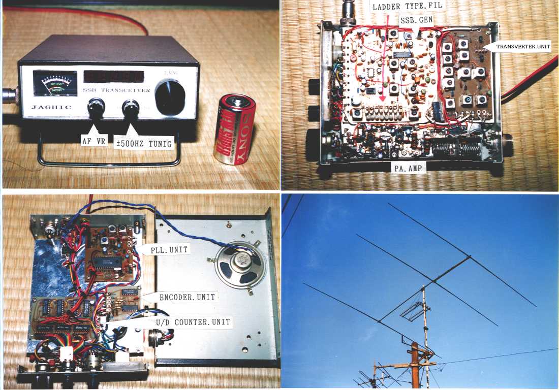
Front control panel layout (dials and volume controls)
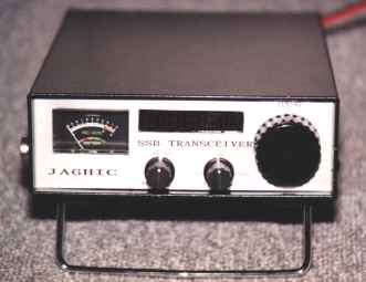
The photo above is a front view of No. 5. On the left is the S meter, the top center is the digital frequency display, and the knob on the bottom left is the Audio volume control.
The knob on the bottom right is a volume knob with a center detent. At the center position, the frequency is zeroed in exactly at 1 kHz. Turning this volume knob to the right allows you to vary the frequency by +500 kHz. Conversely, turning it to the left allows you to vary the frequency by -500 Hz. Since most stations will come out with the frequency zeroed in exactly at 1 kHz, stations other than those using an analog VFO will not operate at any position other than the center detent. Furthermore, by pulling this knob towards you, the antenna wire is connected directly to the input of the SSB generator, allowing you to receive 15 MHz standard radio waves.
The large knob on the far right is the main frequency variable dial, which allows you to adjust the frequency up or down in 1 kHz steps. As mentioned above, most stations are transmitting at a frequency in the 1 kHz range, so you can zero in on the other station's frequency just by operating this main variable dial. Occasionally, there are stations using older analog VFOs or stations that deliberately set their frequency to the middle 500 kHz, in which case you can adjust the frequency using the knob with a center click at the bottom right.
The case we use is 15cm wide x 5cm high x 20cm deep, and is a commercially available product called FM50 from Suzurando.
Top surface board layout (explanation of the boards arranged on the top surface)
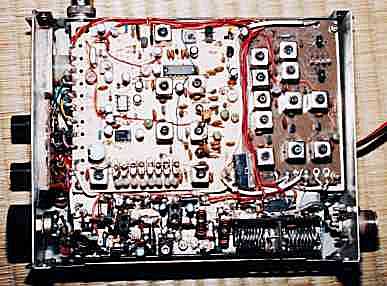
To make it as small as possible, the case has a sandwich structure. Specifically, an aluminum plate is placed inside the case to separate the top and bottom, and the SSB generator, transverter, and final power amplifier are mounted on the top, while the PLL circuit and the digital circuitry that controls it are mounted on the bottom.
The photo above shows the top side of the divider. The upper left is the SSB generator board. The filter is a ladder type using eight 15MHz crystals (100 yen each, purchased from Ikeda Electronics).
The upper right part is the transverter, which converts 15MHz signals to 21MHz. Of course, this part can be used for both transmission and reception. The long, thin part at the bottom is the final stage power amplifier. The final stage transistor is a 2SC1957, and the maximum output is 3W.
Bottom board layout (Explanation of the boards located on the bottom)
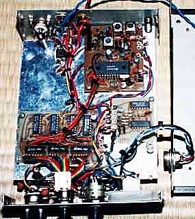
The photo above shows the underside of the partition plate. The PLL oscillator circuit board is on the top right, the small board to the bottom right of that is the dial encoder board, and the board for the up/down circuit that controls the PLL circuit is on the bottom left.
The PLL circuit oscillates in the 60MHz range (10kHz step), and the divider IC divides it by 10 to produce a 6MHz range (1kHz step). This 6MHz local oscillator output is mixed with the 15MHz IF to produce a 21MHz signal.
The adjustable frequency is 21.000MHz to 21.899MHz (899kHz). Adjustments below 1kHz are made possible by using a VXO to control the PLL reference oscillation crystal, allowing for adjustments of ±500Hz.
No.5 performance
The No. 5 unit introduced here has the following characteristics. All other characteristics except for the current value during transmission and reception were measured by Kikuchi OM (JA1HWO)
| * Receiving current |
|
225mA | (*Current value when silent) |
| * Peak current during transmission |
|
795mA | (*Current value when output is 3W) |
| * Output second harmonic |
|
-52dB | (*Standard value -40dB or less) |
| * Output third harmonic |
|
-60dB or less | (*Standard value -40dB or less) |
| * Career suppression |
|
-48dB | (-52dB at 21.45MHZ) |
| * Spurious (VFO x 3) |
|
-66dB | (*VFO x 4 is -65dB) |
| * Transmit power |
|
3W | (※2.8W at 21.45MHZ) |
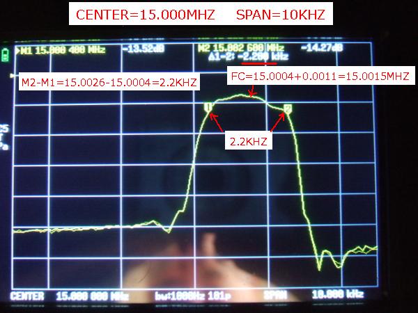
| * 15MHZ filter characteristics |
|
-6dB BW 2.2KHZ | -60dB BW 4.1KHZ |
*All of the above measurements are taken when the power supply voltage is 13.0V.
Introduction of circuit diagrams and print pattern diagrams for each unit
This concludes the overview of Unit No. 5, but for those who would like to see more details, we have provided the circuit diagrams and printed pattern diagrams below. If you are interested, please take a look.

Spurious Measurement
| Measuring instruments used and the measurement scene
|
 |
|
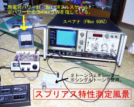
The photo on the left shows the measurement of the spurious characteristics of unit No. 5.
I connected the single tone of the two-tone generator to the microphone input and measured the spurious signals at full power (3W).
Since this was a rare opportunity, I measured not only the final output but also the four points described in the next section.
The spectrum analyzer used for the measurements was TAKEDA RIKEN's TR4110 (TRACKING SCOPE) + 4111A (RF SECTION).
|
|
|
The measurements were taken in order, starting from the collector output of the final stage transistor.
The specific measurement points are the four locations shown in the diagram on the left.
|
| Measurement point 1 (immediately after the final stage transistor) |
 |
|
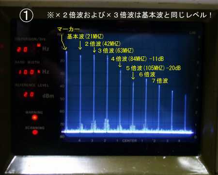
The photo on the left is taken immediately after the collector output of the final stage transistor.
Naturally, this is spurious noise when no filters are used.
Surprisingly, the second harmonic (42 MHz) and third harmonic (63 MHz) were almost at the same level as the fundamental wave.
In other words, the harmonics of 42 MHz and 63 MHz also produce the same level of output as the fundamental wave!
If an antenna is directly connected here, a lot of unwanted radio waves will be emitted, which will result in inconvenience to many people.
|
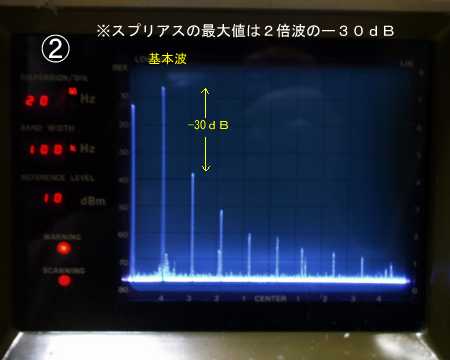
| Measurement point 2 (immediately after the T-type filter) |
 |
|
The photo on the left shows the spurious signal immediately after the T-type filter.
Compared to the case without a filter, the level of the harmonics is indeed lower. However, the level of the second harmonic is -30 dB compared to the fundamental wave. This does not meet the -40 dB limit set by the Radio Law.
There is a design method to increase the QL of the T-type filter, but this will result in inconveniences such as increased pass loss and narrower bandwidth. Considering these points, it is clear that a wideband amplifier cannot be made with just one stage of T-type filter.
|
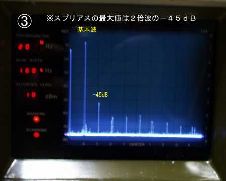
| Measurement point 3 (immediately after the first low-pass filter)
|
 |
|
The photo on the left shows the spurious signal generated after a low-pass filter is inserted after the T-type filter.
Although only one low-pass filter is added, the level of the second harmonic wave is reduced to -45 dB.
In this state, it meets the radio wave regulation of -40dB or less.
Although it is clear, it is only -5dB, so it would be safer to add another stage here.
|
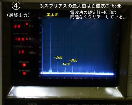
| Measurement point 4 (spurious at final output) |
 |
|
The photo on the left shows the spurious emissions at the final output.
The maximum value of the spurious is -55dB of the double wave.
The third harmonic wave is -62dB and the fourth harmonic wave is -60dB, which are completely acceptable values.
Adding a low-pass filter only requires a small amount of tin-plated wire and two capacitors. It's better to use more filters than necessary, as it will give you peace of mind.
|
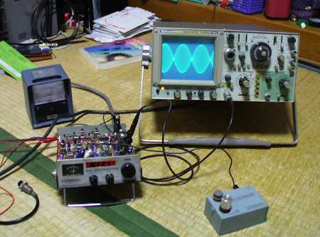
Local oscillator spurious characteristics and two-tone waveform of final stage power amplifier output
Since I had the opportunity to take the time to measure it, I also took the opportunity to observe the spurious characteristics of the local oscillator and the two-tone waveform at the final output of the final stage power amplifier (measurement point 4 in the previous section).
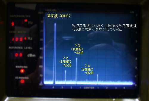
In particular, the local oscillator's double wave (12 MHz) needs to be kept as low as possible, since the IF is set to 15 MHz. If the level of this double wave is too high, 15 MHz + 12 MHz = 27 MHz, and the old 27 MHz band of CB radio will be directly received. (The station's location is only about 250 meters in a straight line from the national highway, making it susceptible to interference from CB radio.)
The old CB radios have lost their former popularity, but they are not completely extinct. If you listen to them, you can still hear the whistling sound of standby radios.
The measurement results showed that the multi-stage filter was effective, and the second harmonic (12 MHz) at the final output stage of the local oscillator was -55 dB compared to the fundamental wave (6 MHz).So far, there has been no interference from signals in the 27 MHz band, so it seems that there are no adverse effects from this harmonic (12 MHz).
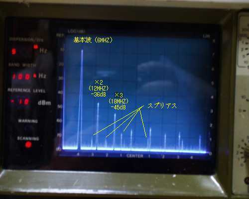
| Local spurious measurement points |
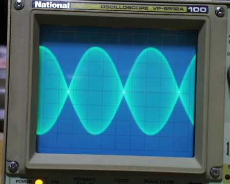
Local oscillator spurious generation and two-tone waveform at final stage output
(Click on each photo to see an enlarged version)
 |
 |
 |
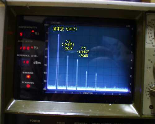
| Measurement point 1 |
Measurement point 2 |
Measurement point 3 |
 |
 |
 |
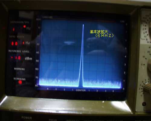
| Main carrier expansion |
Waveform observation |
Two-tone waveform |
 Return to the homepage
 Contest Contact Video using Unit No.5(YouTube)