Adjustment accessories
(Last updated October 1, 1998)
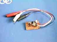
Simple High Frequency Probe
When working with radio equipment, there are many cases where you need to find the maximum output point by adjusting the coil or trimmer. This simple high frequency probe is a handy tool when you want to know the rough level of the high frequency part.
Although it is not possible to read the exact voltage (absolute value), the output changes depending on the input, so the maximum and minimum values can be determined.
In my case, my tester has a relatively high sensitivity (full scale 60μA), so I connect it to the output of the probe. Generally, people connect a junk meter such as a radio (tuning meter attached to a cassette tape or radio) and use it.
If you use a meter with as high a sensitivity as possible, it will be easier to use because the meter will fluctuate even with low-level signals.
The smaller the capacitance of the input coupling capacitor marked with an * on the circuit diagram, the less adversely it will affect the circuit. However, if it is made too small, the output level will drop, and if a meter with poor sensitivity is used, the meter will not deflect and will be difficult to use. It is best to use a meter with high sensitivity (around 100 μA) and a coupling capacitor of around 10 pF.
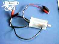
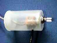
Because it is a very simple circuit, I attach the components to a snake-eye board and place the entire circuit in the film case shown in the photo on the far right below.
When adjusting an SSB transmitter, output is only produced when modulation is applied, so audio input such as a whistle is required.
If the adjustment is completed in a short time, you can continue whistling, but in most cases, you will end up whistling too much and feeling dizzy, just like in a cartoon. Also, it is surprisingly difficult to keep whistling at the same level continuously.
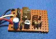
In such cases, this AF oscillator is used by connecting it to the microphone input. The time constant of this circuit outputs an AF signal of about 1000 Hz.
To use it, connect the output of this AF oscillator to the microphone input of an SSB generator, which will produce a continuously modulated high-frequency output. This high-frequency output can then be read with the high-frequency probe described above, and each coil in the transmitting system can be adjusted accordingly.
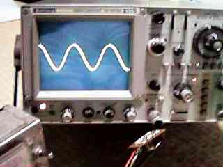
This circuit is also relatively simple, so I built it using a Janome board. Considering how simple the circuit is, it produces a relatively clean sine curve output. The photo on the far right below shows the output of this AF oscillator as seen through a synchroscope.
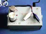
Two-Tone Generator
A two-tone generator is an invaluable tool when adjusting an SSB transmitter. Of course, a synchroscope is also required to observe the waveform.
By looking at the two-tone output waveform of an SSB transmitter, you can evaluate whether the transmitter is well-built. For example, the linearity of the final stage power circuit (suitability of idling current, etc.) can be judged by looking at this waveform.
If there is even the slightest problem in the transmitting system, the waveform at the final output stage will be distorted. For this reason, in order to obtain a clean two-tone waveform, it is necessary to start by checking the output waveform of the SSB generator, and then carefully check each circuit up to the final power amplifier as you build the system.
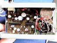
The circuit for this two-tone generator was created based on what OM Niwa (JA1AYO) published in the magazine "Ham's Transistor Utilization." Since there are likely copyright issues with the circuit diagram and pattern diagram, I will only introduce this here as something that I have made. If you are interested in the circuit or would like to try making one, please take a look at the magazine mentioned above.
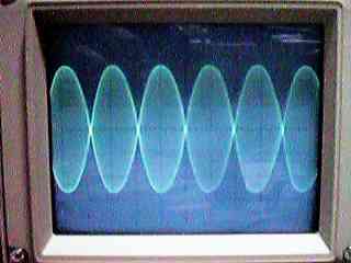
The photo on the far right below was taken using this two-tone generator to measure my No. 5 unit, and shows the two-tone waveform at the output connector (final stage output).
 Return to Home Page