A dip meter is an essential measuring instrument for homebrew hams. Its uses are diverse, including measuring the resonant frequency of coils and antennas. As a homebrew ham myself, I have relied heavily on a dip meter.The dip meter I've used for many years is a vacuum tube type DM-6 made by Trio (the predecessor to the current Kenwood). Perhaps it couldn't withstand years of heavy use, the output power at high frequencies has been weakening for the past few years. This is probably due to a loss of emission from the internal vacuum tube (New Vista). It's virtually impossible to find this type of vacuum tube these days, and the manufacturer probably doesn't even have them available as replacement parts.
Nowadays, it is no longer the time to use AC powered dip meters, so I took this opportunity to make a battery operated FET dip meter. The work introduced here is a dip meter with a built-in LCD display counter, which was completed in January 1995.
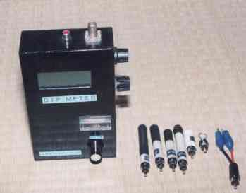
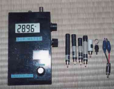
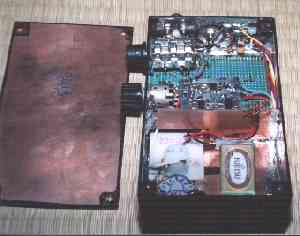
The photo above is a front view of the homemade dip meter. As you can see in the photo on the right, it has a built-in LCD counter and uses five coils to cover the 1.6 to 217MHz range.
The dip meter with built-in counter is very easy to use, and compared to the old scale type that displayed the frequency roughly, it displays the accurate frequency digitally, making it even more useful as a measuring instrument.
Recently, even manufacturers have started selling counter-mounted models, but they cost around 40,000 to 60,000 yen, so they are not something that can be easily purchased. They are out of reach, especially for someone as penniless as me.
There are circuits that use transistors, but previous build articles have suggested that circuits using FETs produce deeper dips. Since dip meters were originally made with vacuum tube circuits, it is easy to deduce that it would be better to use FETs, whose characteristics are similar to those of vacuum tubes.So I searched for a circuit diagram for a dip meter using FETs, and found a suitable circuit in "Encyclopedia of Toroidal Core Applications" (by Hideho Yamamura). The instructions said it was for a toroidal core, but I thought I could make it with the materials I had on hand, so I used this circuit diagram as a reference.
The oscillator circuit uses a 2SK241 FET that I had on hand. Since I wanted to incorporate a frequency counter, I used a low-power LCD counter. I purchased Akizuki Electronics' "1GHz Prescaler + 4.5 Digit LCD Counter Kit" and installed it inside the case.
Once the general circuit configuration was decided, I started thinking about what case to get. I couldn't find a commercially available case that was just the right size. And it would be a pain to make a case by cutting aluminum plate. So I decided to make a case using a double-sided printed circuit board.I purchased double-sided boards from Akizuki Electronics for 1000 yen for 10 pieces and then modified them to make a case. The overall dimensions are 10.1 cm wide, 16.1 cm high, and 4 cm deep.
The six boards that will become each side were cut to the specified size, solder was poured onto the inner joint surfaces, and assembled into a case. Since the other side is a baked double-sided board, processing was relatively easy, and after assembling, there were some slight dimensional discrepancies, and by sanding the outer parts, it looked more realistic. Finally, the outside looked unsightly if left as copper foil, so it was finished with black spray paint.
The circuit for the dip meter is assembled inside the top of the case. Specifically, small lands are attached to the circuit board, and components are attached to the lands. I often use this method in the final stage power amplifier circuit of transceivers.
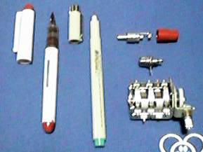
The photo above shows the materials used to make the coils for the dip meter. The pen on the far left is sold under the brand name V-Pen, and the cap of this pen is used as the case for the 95-217MHz coil. The pen second from the left is also sold under the brand name PIGMA, and was used for the bobbins of all coils except the 95-217MHz coil.These pens fit nicely into a male RCA pin jack for audio. The connection between the main body and the coil uses a male and female RCA pin jack.
Specifically, the female RCA pin jack is used on the dip meter case body, and the male pin jack is used on each coil, making it interchangeable. If you use a male RCA pin jack with a threaded cap, it will be easier to process when attaching the bobbin case.
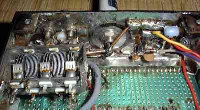
The one on the bottom right of the photo is the variable capacitor used for FM/AM radio. I bought them for 280 yen each, as they were being sold as junk at a ham shop. I happened to be able to get hold of some junk air variable capacitors, so I used those, but of course you can also use the poly variable capacitors built into transistor radios.
I also experimented with using a varicap instead of a variable capacitor, but the frequency variable range was narrower due to the power supply voltage, and I was unable to achieve what I wanted.
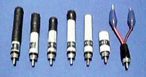
The photo above shows the completed coils. From left to right, they cover the following frequencies: 1.6-5.0MHz, 3.6-11.0MHz, 8.8-29.0MHz, 27-95MHz, 95-207MHz, and 95-217MHz.
The 95-207MHz coil is made with a hairpin structure (U-shaped), while the 95-217MHz coil is made with a regular helical air-core structure (circular).These two coils can be used depending on the location.
The coil winding is easy as it has a built-in counter. Just wind the appropriate number of turns onto the bobbin and let it oscillate. If the frequency is lower than the intended frequency, reduce the number of turns, and if it is higher, add more turns. Adding more turns is difficult, so it is better to wind more turns and then reduce the number. If this does not work, you can also try changing to a coil with a higher frequency.
I cover the finished coil with caltrop tubing (which shrinks when heated) to prevent the coil windings from shifting and to protect them. The one with the alligator clip on the far right of the photo is made to be used for testing purposes by clamping a crystal or similar. I've even tried clamping a paper clip to see how many MHz it would oscillate at.
Unlike the AC corded models we have used up until now, there is no need to prepare a 100V power supply. This is a big advantage when doing outdoor work such as adjusting antennas (especially on top of a tower).The built-in frequency counter displays the frequency in detail, improving the accuracy of adjustments. The counter also uses an LCD display, making it easy to read even in bright places. If an LED display were used in this area, it would be very difficult to see in bright places and would be unusable.
This LCD counter is easy to read in bright places, and also has the advantage of extremely low current consumption. When I was planning to build it, I was thinking of using six AA batteries as the power source, but when I measured the total current consumption after it was completed, it was only 10mA, even with the counter (including the prescaler) and dip meter circuits all running! Therefore, I decided not to use AA batteries, but to change to 006P stacked dry cell batteries to make it lighter. The LCD counter is a bit expensive at 5,700 yen, but you can use relatively cheap junk items for the rest. I think you'll have plenty of change left over for a total of 10,000 yen.
It would be a waste to use the counter only as a dip meter, so I attached a BNC plug to the case so that it can be used as a normal counter. The result is a frequency counter with the dip meter circuitry just getting in the way.
 Return to Home Page