Along with a dip meter, a frequency counter is an essential item for DIY hams. Since you work based on the frequency displayed by the counter, it's natural to want a highly accurate counter, but that doesn't mean it needs to be absolutely accurate.In my opinion, counting errors up to the 10 Hz range are not a problem. This deviation only applies when adjusting the carrier point of an SSB transceiver, and I personally don't think it's a problem since we're not a professional broadcasting station (operating at a fixed frequency) except for operating at the band edge.
As you know, the accuracy of a frequency counter is determined by the accuracy of the reference oscillator. If you absolutely need accuracy, investing in a reference oscillator can solve this problem.
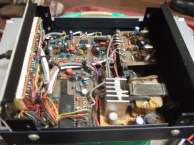
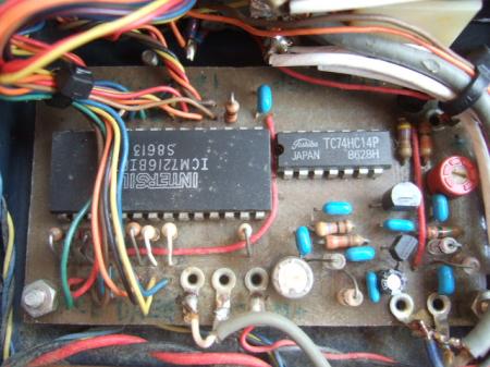
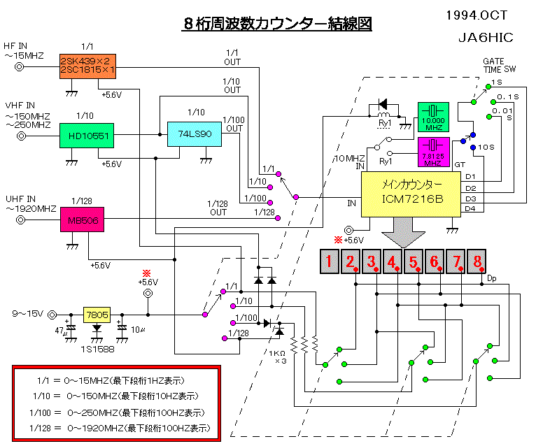
The photo below shows an 8-digit frequency counter completed in November 1994. The main counter IC uses an ICM7216B. The ICM7216B is a dedicated counter IC that incorporates all the functions necessary to configure a counter.
When I think back to the days when we connected multiple TTL decimal counters in stages and made a big fuss about reset pulses and strobe pulses, I feel nostalgic for the hardships we faced, and am amazed at the technological advances in this field.
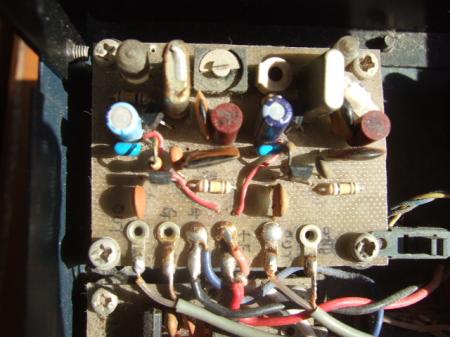
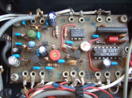
This 8-digit frequency counter consists of four components: the main counter circuit board, the preamplifier and prescaler circuit board, the reference oscillator circuit board, and the power supply circuit board. In the photo on the right below, the preamplifier and prescaler circuit board is located in the upper left, the reference oscillator circuit board in the upper right, the main counter circuit board in the lower left, and the power supply circuit board in the lower right.
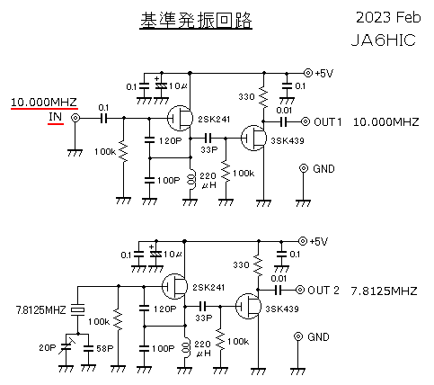
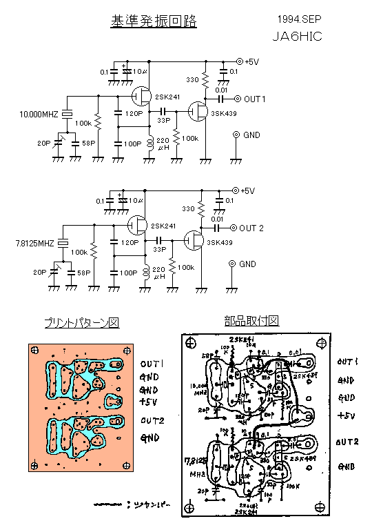
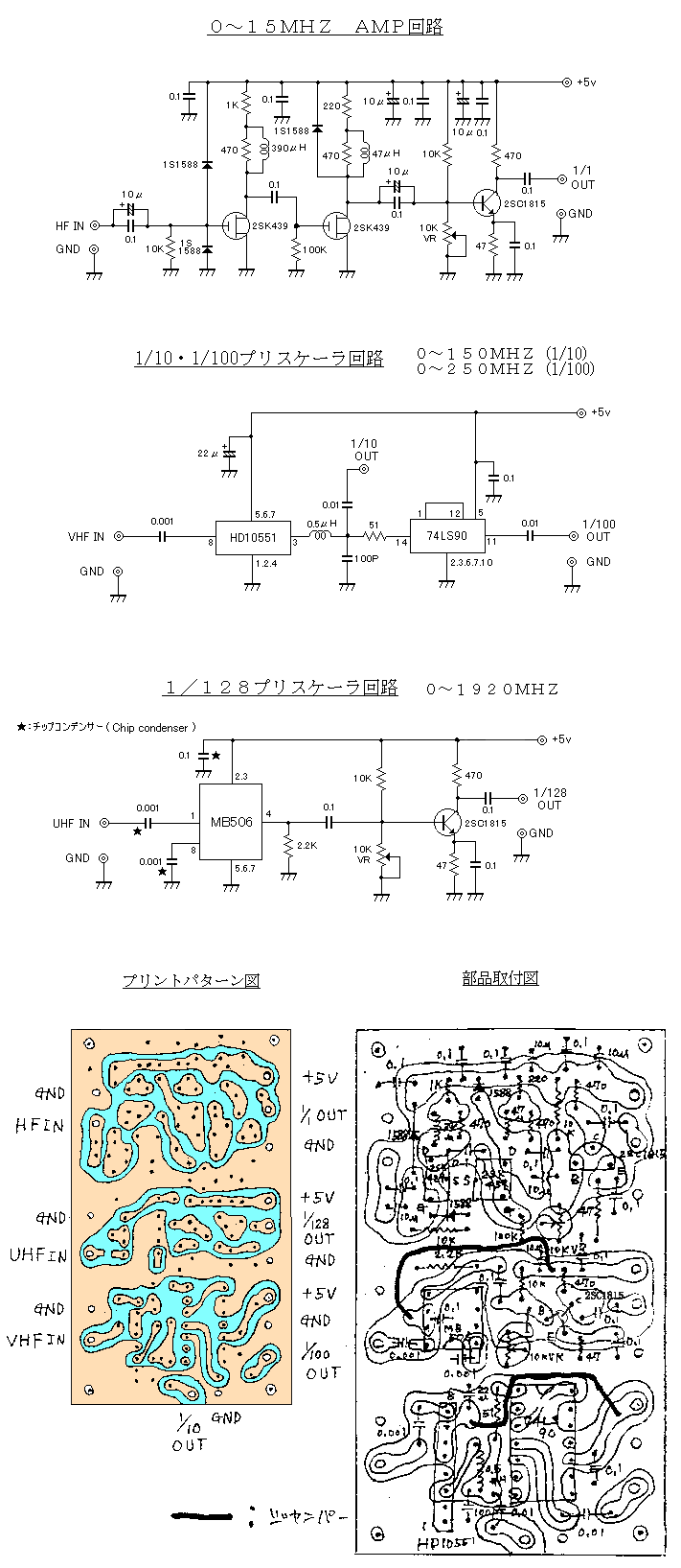
Below are the circuit diagrams and printed pattern diagrams for the three units, excluding the power supply circuit.

My Experience It displays all 8 digits simultaneously, so unlike the 4.5-digit counter mentioned above, there's no need to switch gate times to check all digits. Once you start using the 8-digit counter, you won't want to use a counter with decimal points.
By the way, you may think the reference oscillator circuit is rather poor, but I think it's a waste of money. If you need accurate frequency measurements, calibrating the reference oscillator frequency with JJY (10 MHz standard radio wave) in advance should be sufficient for amateur use (though I'm aware of an error of around 10 Hz).
10MHZ reference oscillator replacement (Some content added February 17, 2023)
Recently, I have been working on improving my own decades-old equipment. Last time, I made an SWR meter, but this time I replaced the frequency counter and the reference oscillator of a YAESU FT-817.This is the first update to the frequency counter in 26 years, since December 15, 1997. Recently, when I contacted a local station, they pointed out that their frequency seemed to be drifting. The cause of the frequency fluctuation is thought to be fluctuations in either the carrier frequency (15 MHz) or the local oscillator (6 MHz). Checking the fluctuations in each frequency with the frequency counter should help identify the cause.
However, the homemade frequency counter introduced here has a simple circuit configuration using general parts for the 10MHz reference oscillator that determines the measurement frequency and stability. For this reason, the accuracy of the measurement results and the stability can be said to be low.
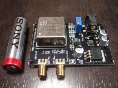
I thought I would like to replace it if I could find one with a more accurate reference oscillator, so I previously purchased a 10MHz reference oscillator with a thermostatic oven at an online auction.However, the oscillator itself was quite large and could not fit into the case of the counter introduced here, so I had no choice but to install the reference oscillator unit externally.
For these reasons, I wasn't very keen on installing the reference oscillator externally, which would make it difficult to use, so I left it alone, thinking I'd work on it at some point. Then I found something on Amazon that looked like it could be used as a 10MHz reference oscillator. The reference oscillator I found looked like the one below.
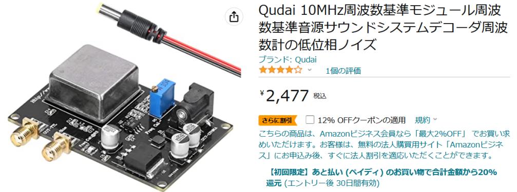
10MHZ oven-equipped reference oscillator available for sale ※The lowest price at the moment is 1,509 yen
*Click on each photo to enlarge it. 10MHz reference oscillator unit
with thermostatic chamber functionI bought it for 2,477 yen. The
lowest price available at the moment is 2,113 yen.Warm-up current: 0.75A for 5 minutes
normal operation current: 0.3A
I immediately started up the reference oscillator I purchased and measured its frequency with my homemade 8-digit counter. The measurement result was 10.000.030Hz, which is about 30Hz higher. I'm not sure if this 30Hz deviation is due to a frequency deviation on the reference oscillator side or an error on the counter side.However, since I couldn't think of any discrepancies in the reference oscillator I purchased this time, I readjusted the 10MHz reference oscillator of my homemade frequency counter so that it displayed 10.000.000HZ. I left it in this state for a few hours and checked the frequency fluctuations.
The measurement results were more stable than expected, with only a 1-2Hz fluctuation observed after leaving it for about 5 hours. I don't know if this fluctuation is due to a deviation in the reference oscillator or the counter, but since the reference oscillator on the homemade counter is poor, I think it's probably due to drift in the reference oscillator on the counter side. Looking at these measurement results, considering the poor reference oscillator of the homemade counter, the fluctuation in the displayed frequency was fairly small, so I felt it wasn't completely useless.
If you think about it, the counter's reference oscillation of 10 MHz is 1/10,000,000 of the original frequency, which is 1 Hz (1 second), and is used as the counter's gate time. Because of this, even if there is a slight drift in 10 MHz, the effect is 1/10,000,000. Therefore, it is thought that the effect of drift is significantly reduced.
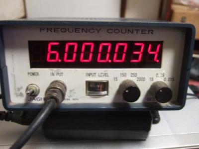
With the test complete, I replaced the counter's reference oscillator with the newly purchased temperature-compensated reference oscillator. Specifically, I removed the crystal from the counter's 10MHz reference oscillator circuit and connected the output of the newly purchased 10MHz reference oscillator with thermostatic oven function to the gate of the 2SK241 to which the crystal was connected via a 0.1μF capacitor. Once the circuit switch was complete, I immediately measured the 6MHz PLL output of the local oscillator of Unit 5.
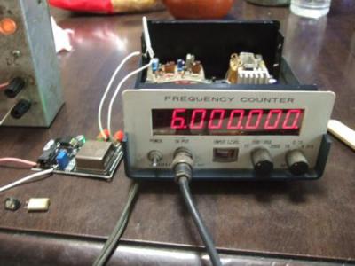
I set the center click volume, which adjusts below 1KHZ, to the center position, fine-tuned the correction volume, and set it to 6,000,000HZ before starting measurements. I left it in this state and checked the displayed frequency after 5 hours.
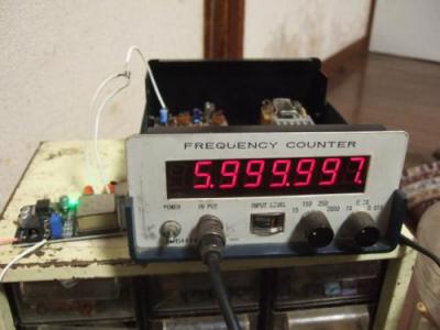
The measurement results showed a very slow frequency fluctuation within the range of +2 to -3 Hz, but five hours after the measurement was stopped, it had dropped to -3 Hz, as shown in the photo below. The maximum value within the observation period was within 3 Hz of the fluctuation. The PLL circuit of No. 5 uses a varicap to adjust below 1 kHz, so I was worried that the frequency drift might be large, but the measurement results were quite good and the numbers were not particularly problematic.
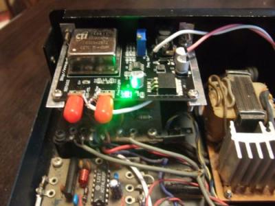
So, after confirming that it was working without any problems, I decided to put the newly purchased reference oscillator inside the case. Looking around the inside of the case, I couldn't find any empty space to install it as it was, so I installed it on top of the existing reference oscillator, like a bunk bed, as shown in the photo on the far right below.
*Click on each photo to enlarge it. Remove the 10MHZ crystal and connect it
to the reference oscillatorI purchased
this time with a 0.1μF resistor.While measuring the 6MHZ PLL
output of unit No.5, what is
the drift after 5 hours?The drift after 5 hours is -3Hz.
The frequency fluctuation
is less than expected.Install the purchased reference
oscillator board on top of the existing
reference oscillator circuit board
After replacing it, I felt like the measurements were very stable. My homemade counter, which had been a little unreliable in terms of measurements, is now something I can use with confidence. (Maybe that's a bit of an exaggeration?)If you have an older counter and the reference oscillation accuracy is not very good, or if you have built one using Akizuki's DIY counter kit and the reference oscillation is not very stable, you can upgrade the reference oscillation by investing just over 2,000 yen, so please give it a try.
Problem with the power supply circuit! (Some content added August 28, 2025)
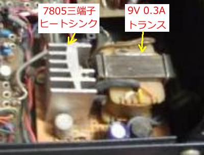
So that would have been a happy ending, but in fact there was a problem with the power supply circuit. The original circuit only required a single 5V power supply. A small AC9V transformer with a current capacity of about 0.3A was used, and the AC9V was bridge rectified using a 7805 three-terminal regulator to supply 5V. Incidentally, the reason why a 1S1588 diode is inserted into the earth connection terminal of the 5V three-terminal regulator is to raise the power supply voltage by about 0.6V. This is a measure to increase the minimum countable frequency of the main counter as much as possible.Before installing this reference oscillator circuit, the actual measured current consumption was approximately 110mA in the 0-15MHz measurement range (main counter and pre-amplifier operating) and in the 0-150MHz and 0-250MHz measurement ranges (prescaler HD10551 operating). When using the MB506 prescaler (main counter and MB506 operating), the current consumption was approximately 180mA. From these results, it can be seen that with the old type, the maximum current consumption in the 0-1920MHz measurement range was 180mA (0.18A), and there were no problems at all even with a miniature transformer with a current capacity of around 0.3A.
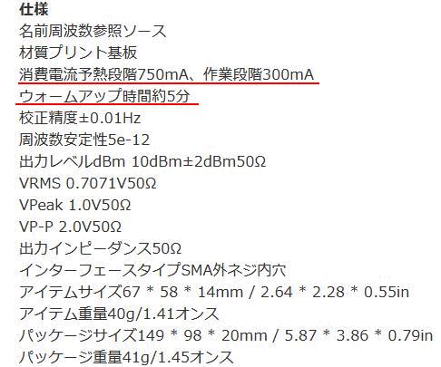
However, by incorporating this 10MHz reference oscillator, the reference oscillator section consumes 300mA of current during normal operation, according to the manufacturer's published figures, and 750mA during warm-up. During normal operation, the counter section and reference oscillator section consume a total of 480mA. While this is a slight overload in this state, during warm-up, the combined current consumption by the counter and the reference oscillator reaches nearly 900mA, significantly exceeding the capacity of the transformer.
When actually operating the unit and looking at the LED display, the display was dark until the warm-up was complete, and it was clear that a voltage drop had occurred. Also, even after a short time in normal operation, the transformer began to heat up due to overload, and it was clear that the power supply circuit needed to be strengthened.
A 10MHz reference oscillator circuit requires a power supply voltage of 7 to 13V and a current capacity of at least 1A. Taking this into consideration, a circuit using a normal transformer would result in a transformer that would be too large to fit into the current case. This is why I came up with the idea of ??using a switching power supply.
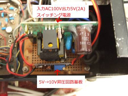
Specifically, I decided to use a switching power supply with a power supply voltage of 5V and a current capacity of 2A. I searched through a junk box and found an I-O DATA 5V 2A switching power supply lying around. It was in a black rectangular case, and the input side had a two-prong AC 100V plug. I removed the plastic outer box and extracted only the contents. All that was left was a 7-13V power supply, and I found a unit on Amazon that could boost a 5V input to around 28V.
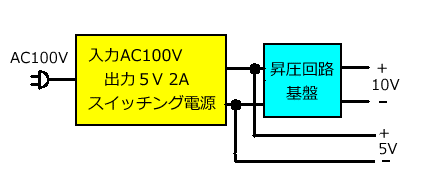
By combining these two power supply units, we prepared a 5V single power supply for the counter circuit, including the prescaler, and a 10V single power supply for the 10MHz reference oscillator circuit (the reference oscillator circuit board was printed with a power supply voltage of 7 to 13V, so we set it to the middle value of 10V). Please see the image below for the connection and installation of these two units.
*Click on each photo to enlarge it. The original power supply unit was
0.3A.A small transformer was used.5V switching power supply
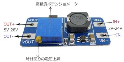
and Booster CombinationWhen 5V is input, up to 28V It seems
that the voltage can be increased5V switching power supply Connect
a boost circuit to the output
For reference, a 5V 2A switching power supply and boost unit are sold on Amazon, so I've included a link below.
*The input is 2 to 24V, but it does not actually work with voltages above 5V.
I think it can also be used by inputting a lithium battery (1 cell 3.6V) and outputting 5V or 9V.
"At the same time" I also replaced the reference oscillator of the FT-817
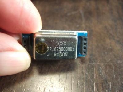
I also replaced the 22.625MHz reference oscillator in my YAESU FT-817 with a highly stable TCXO. This was because I wanted to monitor and check the frequency fluctuations using the FT-817. However, if the frequency of the receiver being monitored is not stable, it will be impossible to compare.I had been thinking about replacing it for a while, but at the time it was about 9,000 yen, so I hesitated. However, when I checked Amazon last December, I found a compatible part for about 1,600 yen. The price difference with the genuine part was so big that I wondered if it would even be useful, but since it was only about 1,600 yen, I decided to buy it anyway.
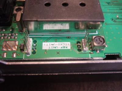
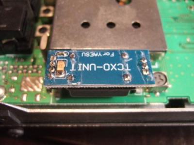
Replacing the parts was very easy and did not require any soldering or other work; the work was completed by simply pulling out the existing reference oscillator unit by hand and inserting the new unit by hand. When replacing the unit, the original unit had 3P and 4P through holes in the printed circuit board, with the part mounting surface facing up. The unit purchased this time did not have these holes, so it could only be mounted with the printed circuit board surface facing up, as shown in the photo below.
I was worried about whether this was the right direction, but since I couldn't install it with the part mounting surface facing up, I installed it in the direction shown in the photo. Worried about whether it would work, I turned it on and tried it out, and it worked without any problems. After the replacement was complete, I immediately turned on the FT-817 and let it age for about an hour, then received a 10MHz JJY signal to check for any frequency discrepancies.
Here I will explain the specific method I use to check the time. First, receive the standard time signal. In this case, select the strongest standard time signal from 5MHz, 10MHz, or 15MHz. It is easier to judge if the reception mode is set to SSB mode. The mode can be either USB or LSB. If you check the LSB setting, switch to USB after checking and check the deviation again.
In this case, if the received JJY signal is weak, you won't be able to hear a beat sound with a frequency of a few Hz. If you connect a reliable antenna and, ideally, have a signal strength of around 9+, you should be able to hear a beat sound with a frequency deviation of a few Hz. If you turn up the volume while receiving a strong JJY signal, a beat sound will be heard in proportion to the frequency deviation. If the deviation is a few Hz, a popping sound will be heard from the speaker. If you are adjusting the frequency by varying it, adjust the frequency so that the intervals between these popping sounds become wider. When the frequency is correct, the intervals between the popping sounds will become wider, and eventually you will hear a buzzing sound (zero beat sound), indicating that the frequency has been adjusted.
If you hear a buzzing zero-beat sound at this time, it means that the receiver is receiving the correct frequency. If you hear a popping sound, it means that the receiver is off by a few Hz. You can check how much the frequency is off by adjusting the frequency with the dial. On my FT-817, the lowest frequency setting is in the 10 Hz range, so unfortunately I cannot check for deviations below 10 Hz.
This method checks whether the frequency is correct as a whole for the receiver; if it is off, you need to check the individual units that affect the receiving frequency configuration and correct the discrepancy. As an aside, I also use this method when tuning the carrier frequency of an SSB transmitter. I bring the receiver's antenna wire close to the transmitter's SSB generator to receive the SSB signal. At this time, the receiver frequency is tuned to the carrier frequency. In the case of my No. 5 unit, it is USB 15,000 MHZ.
In the case of a transmitter, the microphone causes a high-pitched howling noise. When the frequency is perfectly matched, a continuous beep sounds. Of course, the receiver's accuracy is an issue with this method. If using a standard receiver, it goes without saying that the frequency accuracy of that receiver will be adjusted accordingly.
Using the above measurement method, I found a discrepancy of about 0.5 Hz compared to the 10 MHz JJY. There appears to be a frequency adjustment trimmer, but I didn't adjust it because messing around with it could actually cause problems. This level of frequency discrepancy is not a problem for amateurs. It was a cheap 1,600 yen reference oscillator, but it was pretty accurate. I'm curious to see how much difference in accuracy there is between a genuine product costing around 9,000 yen and a 1,600 yen knockoff (sorry! compatible product), but it may actually be quite similar.
I found a blog post by someone who actually measured the frequency fluctuations of a standard-mounted TCXO and a compatible TCXO. Since the standard-mounted TCXO is not a TCXO, it seems that the frequency fluctuates quite a bit. The actual measurement results showed a fluctuation of about 15 Hz over a 30-minute period. On the other hand, the compatible TCXO also showed almost no frequency fluctuations, and there were no stability issues for the price, so it seems there are benefits to replacing it.
Using the above measurement method, the result was a deviation of about 0.5Hz. This degree of frequency deviation is not a problem for amateurs. It was a cheap 1,600 yen reference oscillator, but it was pretty accurate. I'm curious to see how much difference there is in accuracy between a genuine product that costs around 9,000 yen and a knock-off (sorry! compatible) that costs around 1,600 yen, but it may actually be almost the same.
I found a blog that measured the frequency fluctuations of a standard TCXO and a compatible TCXO. The standard TCXO is not a TCXO, so it seems to have quite a bit of frequency fluctuation. On the other hand, the compatible TCXO also showed almost no frequency fluctuation, and there were no stability issues considering the price, so it seems there are benefits to replacing it.
Comparison of frequency fluctuations between standard mounted products and the compatible TCXO that was replaced. *Measurement results of frequency fluctuations between standard mounted products and the compatible TCXO that was replaced are reported.
*Click on each photo to enlarge it. The reference oscillator is in the lower
left corner.The existing part has
been pulled out and removed.Enlarged view of the reference oscillator
mounting area. 4P on the left and 3P
on theright are connected via pins.The 4P socket is visible on the
right side of the new reference
oscillator to be replaced.Align the 3p and 4p pins and insert
the reference oscillator
to complete the replacement.
If you own a YAESU transceiver FT-817/857/897 and haven't upgraded your reference oscillator yet, why not consider upgrading it now, as it's only an investment of about 1,600 yen? The price includes tax, and shipping and convenience store transfer fees are free.So, to address the frequency drift issue with my homemade transceiver, I measured and readjusted the frequency using an FT-817 with a replaced reference oscillator and a frequency counter with a replaced reference oscillator. I also checked the frequency drift for a little longer, but as far as I could see, there was no significant frequency drift.
I plan to have the local station that pointed out the frequency drift listen to it and get a report on whether there is any frequency discrepancy or drift. I'm checking it with measuring equipment that I believe has improved in accuracy (the receiver is also a good measuring instrument), so I don't think there's a problem.
 Return to Home Page