If you make your own antenna and want to check its matching condition (SWR), you will need an SWR meter. Of course, there are many commercially available products, so it would be easy to just purchase one, but that would be boring for an amateur radio operator.Is it difficult to make your own SWR meter? It seems that those for the 1200MHz band require know-how that cannot be shown in a wiring diagram, but for those up to the 50MHz band like this one, if you make it according to the specifications, anyone can make one with similar performance.
The SWR meter introduced here is a type called a CM type, which can measure SWR from a power of about 0.5 W. For this reason, we have deliberately named it "for QRP."
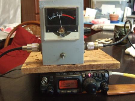
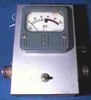
Of course, it can be used at high power without any problems. A performance feature is that if the power is the same at high and low frequencies, the meter will deflect in roughly the same position. The SWR meter I made looks like this:
The circuit of the SWR meter is as follows. This circuit is a slight modification of the one introduced in "Encyclopedia of Toroidal Core Applications" (by Hideho Yamamura).
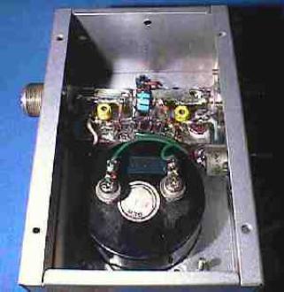
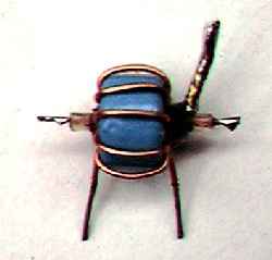
The detector, which can be said to be the heart of the SWR meter, has a structure as shown in the photo below. Since the fine details cannot be seen in the photo, we will explain how it is made step by step. Photo of detector JPG 16kb
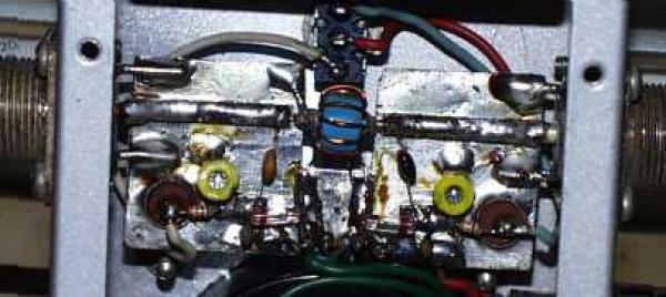
The base board is a bare double-sided printed circuit board (unprocessed board). On top of the bare board, two long, narrow lands with a width of 2.7 mm are attached, which serve as 50 ohm transmission paths, and several small lands for attaching other components. It is difficult to describe the specific structure in words, so it may be easier to understand it from the cutaway diagram. Please see the diagram below for details. Base board structure diagram gif 6kb
Wind 10 turns of 0.5 mm enameled wire around an FT type ferrite core. Pass a short, terminated coaxial cable through the core around which the coil is wound. Pull out the outer braided wire from only one side of this coaxial cable. See the cutaway diagram below for the specific structure.
Once the base board and coil section are complete, we will attach each component to the base board. Please refer to the component layout diagram below for specific component placement. Since the frequency handled is up to 50 MHz, it is not too difficult, but it seems to work best if the components are attached as symmetrically as possible.
Finally, you attach the base board to the case. You need to connect the base board to the M-type connector and secure the board firmly. To do this, I use 1.6 mm bare copper wire to secure and connect the board. Please see the cutout diagram below for the specific method.
、Once the assembly is complete, adjustments are required, which simply involve adjusting two 40PF trimmers. Specifically, input the signal of the highest frequency you will be using (28MHZ or 50MHZ) into the input side, and connect a dummy load with as little reflection as possible to the output side. In this case, the input side can be either the left or right connector facing the meter, but in my case, I use the left side as the input side (radio side) and the right side as the output side (antenna side).
When you switch the meter selector switch with a signal input, one of the meters should deflect less. With the selector switch set to the side with less deflection, adjust the 40PF trimmer so that the meter deflection is at its minimum. At this time, turn the level adjustment volume all the way to the maximum sensitivity side, and adjust it while the meter deflects as much as possible.
Next, reconnect the input and output (signal input side and dummy load connection side) in reverse, input the signal in the same way, and adjust the 40PF trimmer on the opposite side to the trimmer you just adjusted so that the meter deflection is minimized.
At first, you may not know which 40PF trimmer to adjust, but adjust the trimmer that changes the meter's deflection. However, the second adjustment trimmer, which is made by reversing the connections, must be the trimmer opposite the one you adjusted the first time.
Once you have completed the adjustments up to this point, return to the original connection and readjust, then readjust again with the reverse connection and the adjustments are complete.
、To use it, first switch it to the forward wave side, then adjust the volume so that the meter is exactly at full scale. Next, switch it to the reflected wave side, and read the SWR value from the position of the meter needle.
The quickest way to scale the SWR value is to connect a 75 ohm load resistor to the antenna side of the SWR meter, adjust the traveling wave side to full scale, then switch to the reflected side and the position where the needle indicates SWR 1.5 is probably the easiest way.
In normal operation, there should be no problem if the antenna SWR value is 1.5 (reflected power 4%) or less, so it would be good to know the position of the standard SWR 1.5. After that, I think it would be enough to just keep adjusting the antenna until the reflected wave gets as close to 0 (1.0) as possible until the user is satisfied.
、
Meter replacement (Some content added January 13, 2023)
This is the first update in 25 years, since August 9, 1998. When I made this SWR meter in 1998, I frequently used it to adjust my 3EL ZL Special because it was small and lightweight. When I use an SWR meter, I try to use it as close to the antenna as possible, because I thought that an accurate SWR measurement of the antenna would be impossible if a coaxial cable were in the way.When measuring by inserting a coaxial cable midway, it seems that the same results as measuring right next to the antenna can be obtained by making the length of the coaxial cable an integral multiple of 1/2 wavelength. However, making this cable is quite difficult, and using an analyzer or dip meter to accurately cut out the length is a rather time-consuming and tedious task.
Last year, I had many opportunities to use an SWR meter while maintaining the ZL Special antenna, but in each measurement, I measured the SWR not right next to the antenna, but with the coaxial cable in the middle. On the other hand, in the measurement around 1998, I climbed a concrete pillar and was able to measure right next to the antenna, so I was able to measure according to the principle.
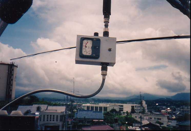
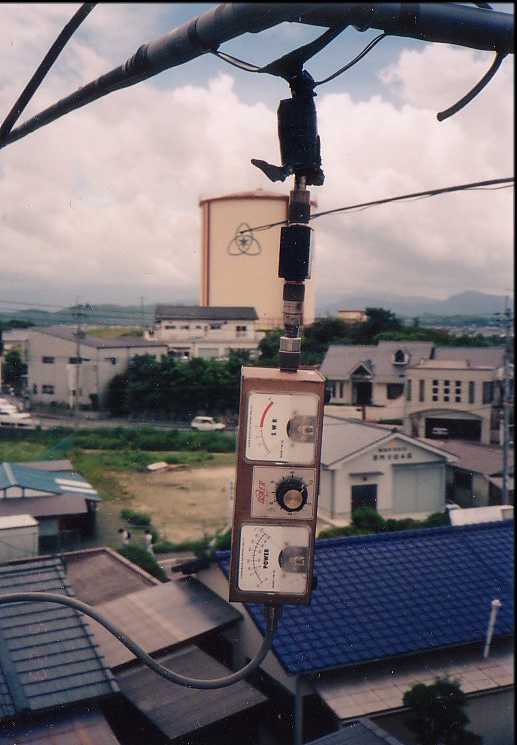
*Click on each photo to enlarge it. Measuring SWR with a homemade SWR meter
placed close to the antenna (around 1998)Reconfirmed using a heavy
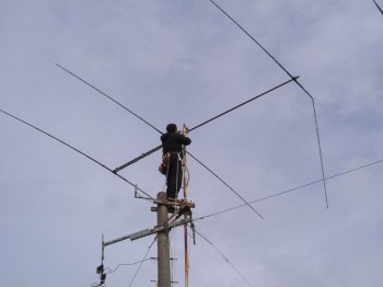
manufacturer's SWR meter (around 1998)Confirming the resonant frequency close to the antenna using RF-1 (around 1998) Once upon a time, I climbed to the top of a concrete pillar
to perform maintenance on an antenna.
However, at the end of September 2022, the antenna installation location was changed from a concrete pillar to the garage roof, making it difficult to work in close proximity to the antenna using a large and heavy SWR meter. For this reason, recently, most of the measurements have involved a coaxial cable.I had a strong desire to measure SWR close to the antenna like in the old days, so I started thinking about refurbishing and reusing the SWR meter I made 25 years ago. However, the SWR scale of the original meter was only approximate, and I hadn't been able to verify how its performance compared to manufacturer's products.
Regarding the SWR scale, in the last update 25 years ago, it was recommended to connect a 75 ohm dummy resistor to simulate an SWR of 1.5 and check the SWR 1.5 position on the meter, but I calculated the relationship between the ammeter reading and SWR when using a 100 μA ammeter. The results are shown in the table below.
The way to read this table is that 20 μA on a 100 μA ammeter corresponds to SWR 1.5, 33.4 μA to SWR 2.0, and 50 μA to SWR 3.0. The 33.4 μA position for SWR 2.0 is a bit tricky, but the ammeter scales for SWR 1.5 and SWR 3.0 are clearly visible, so you can mark these positions on the front cover of the ammeter beforehand.Looking at the results of this calculation, I suddenly thought that if I could get an ammeter with an SWR scale, there would be no need to mark the front cover. A new 100μA ammeter also seems to cost around 1000 yen . Taking that into consideration, if I could get a cheap used meter with an SWR scale, I could save myself unnecessary trouble and it would also look better.
Last year, I happened to come across a meter with an SWR scale on sale at an online auction. I decided to bid on it anyway. I left it there, thinking I would replace it eventually. The ammeter I won at that time was the one shown in the photo below.
It got cold and I couldn't do any outdoor antenna work. At that time, I remembered that I hadn't finished replacing the SWR meter. I replaced the meter to kill time.
The ammeter I originally installed was a moving coil type manufactured in 1970 (the meter has a round seal from Kato on the back of the meter, dated April 27, 1970), and was quite heavy with a sturdy structure, weighing about 140g for the meter alone. However, the one I installed this time was mostly made of plastic and was very light. It was probably the other half of the one that was attached to the manufacturer's SWR meter.
I think the winning bid was around 800 yen. After replacing the meter, the total weight of the SWR meter was 240g. It is very light because it only uses an aluminum case and a plastic meter. With this weight, you can hang it near the antenna's feed point and take measurements, making it possible to measure very close to the antenna.
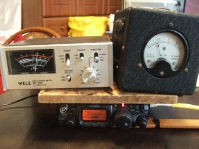
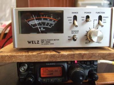
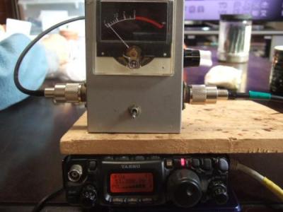
Since I've just replaced the meter and am running it for the first time in a while, I readjusted and calibrated the two 40PF trimmer capacitors on the 50MHz band. I also measured the minimum measurable power. I compared the results on two bands, the 1.8MHz band and the 50MHz band. The results showed that the traveling wave exceeded full scale at 0.5W on both bands. This means that a power of around 0.5W is sufficient for measurement.Since this was a rare opportunity, I decided to check the power measurable by my manufacturer's SWR meter, the WELZ SP-350. At a power of 0.5W on the 50MHz band, unfortunately, the traveling wave meter did not reach full scale, even with the volume control at its maximum position. This means that the WELZ SP-350 cannot measure at a power of 0.5W. However, since you probably won't be measuring SWR at around 0.5W, this shouldn't be a problem.
Next, I looked at the difference in SWR value for each band when the passing power was 5W and 0.5W. It would be nice to be able to compare it with a high-power radio of around 100W, but unfortunately I don't have a radio at home that can output more than 5W, so the high-power side is limited to 5W.
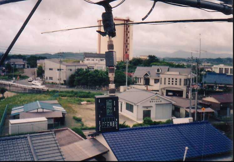
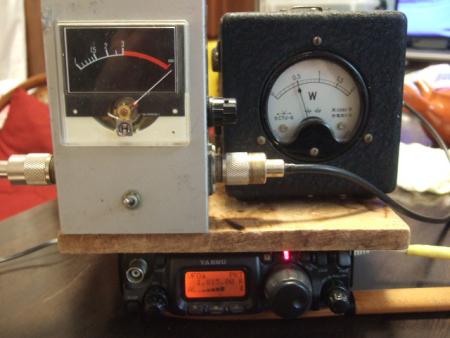
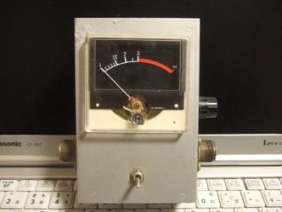
The measurement results were as shown in the photo below. At 51.580 MHz and 5 W of power, the SWR was 2.3. When the power was changed to 0.5 W at the same frequency and the SWR was measured again, it was 2.1. Of course, this is the SWR value after adjusting each traveling wave to full scale. When the power was 1/10, the SWR difference was displayed as about 0.2 lower.
If we consider the increase quantitatively, we estimate that the SWR was 2.3 when the power was 5W, so if the power was 10 times as high, at 50W, the SWR would probably show 2.5. In any case, the actual measurements showed that although there is a slight effect due to the power, the difference is not that great. However, since we only compared powers of 0.5W and 5W, this may not be very useful as a reference.
*Click on each photo to enlarge it. At 0.5W in the 1.8MHz band, the
travelin wave side exceeded full scale.With the WELZ SP-350, the traveling wave
side only swings at a maximum of about 60%.The SWR at 51.580MHz
power 5W was 2.3.The SWR at 51.580MHz power 0.5W
was 2.1, the difference was 0.2.
Comparison of SWR values between manufacturer-made and homemade
I found that the homemade SWR meter was more sensitive. So I measured the SWR with the WELZ SP-350 using a 50MHz IV wire Yagi antenna that I made in a separate article as a load, and then replaced the SWR meter with the homemade one and compared the SWR values.When measuring, I set the frequency so that the SWR meter would show a high reflected wave. The results were as shown in the photo below. The SP-350's SWR was 1.8. The homemade SWR meter showed 2.25.
The SP-350's SWR is 1.8, while the homemade one is 2.25, which is a slight difference. The homemade SWR meter has a larger fluctuation, so it seems to have better sensitivity. It may be picking up weak reflected waves reliably. Just to be sure, I measured the SWR at the antenna's resonance point of 51.200 MHz and it was 1.09, which was almost the same as the SWR value of the SP-350.
Before performing this measurement, when a professional dummy load was used as the load and the trimmer capacitor was adjusted so that the reflected wave was 0 at 50MHz and 5W, the meter reading still indicated almost 0, so the measured reflected wave value is considered to be correct.
Now that I think about it, I remember that the values measured with the antenna analyzer NanoVNA were about 0.2 to 0.3 higher than those measured with the WELZ SP-350. Perhaps the measurement results are similar to those of the NanoVNA. I'm not sure which number is correct, but for now I'm going to assume that the homemade one with the higher number is correct and proceed with the antenna modification work.
*Click on each photo to enlarge it. At 0.5W in the 1.8MHz band, the
traveling wave side exceeded full scale.With the WELZ SP-350, the traveling wave side
only swings at a maximum of about 60%.The SWR at 51.580MHz
power 5W was 2.3.The SWR at 51.580MHz power 0.5W
was 2.1, the difference was 0.2.
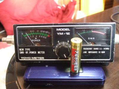
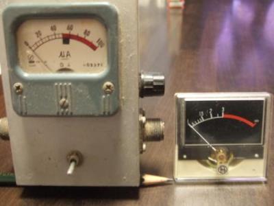
By the way, if you were to build your own SWR meter, it would likely be quite expensive if you bought all the parts. The small SWR meters on the far right of the photo above, which are sometimes offered at auctions, are often designed for high frequencies, and because they use a different method of detecting signals, they have poor sensitivity in the HF band, meaning that you need to apply a considerable amount of power to measure SWR.So I actually measured the SWR of the device in the photo on the far right above using a 3.5MHz band signal. The usable frequencies are 3.5 to 145MHz, but even with the sensitivity adjustment volume set to maximum sensitivity at 5W in the 3.5MHz band, the pointer only swung to about 15% of full scale. Even at 10W, it probably wouldn't reach full scale, so SWR measurement would be impossible.
These items can be purchased at a relatively low price, so I think you can make your own at a fairly low cost by modifying them. Specifically, you can reuse all the main components, such as the case, two meters, two signal detection diodes, two M-type connectors, and a dual volume for adjusting sensitivity, and then make and assemble only the detection unit.
However, when purchasing this type of SWR meter at an auction, it is important to check carefully to make sure the meter is not faulty. In this case, it may be difficult to judge from a photo alone, but if the meter needle is not at zero and is fluctuating even though nothing is connected to the input or output (it is not in operation), it may be best to assume that the meter is faulty.
If you are making your own detector, the detector introduced in the previous section is not that difficult to make, as you can see. The detector uses a 2.7mm wide 50Ω transmission line, but as shown in the diagram below, you can cut the transmission line where the 10PF is connected, connect a coaxial cable there, and then connect both ends of the coaxial cable to the input and output M-type connectors.

The above circuit diagram is for assembling a circuit by reusing parts from a manufacturer's SWR meter with two meters. Since it has a meter for both the forward wave and the reflected wave, there is no need for a selector switch; when the sensitivity adjustment volume is adjusted so that the forward wave meter is at full scale, the deflection of the needle on the reflector side represents the reflected wave (SWR value). It goes without saying that in this circuit, the sensitivity adjustment volumes must be linked and move simultaneously as a dual volume.
If you want to measure SWR in the HF band (especially the 1.8 MHz band) but your SWR meter doesn't measure the traveling wave at full scale, why not try making your own by modifying and reusing a used SWR meter like the one above?
 Return to Home Pag