At first, I built it according to the data in the antenna handbook, but in 1994 I got hold of the antenna calculation software MMPC created by Mr. Matsuda (JA1WXB), and since then I have been building and modifying it based on the data calculated by this software. The Paint screen used in this corner is one created by Mr. Kikuchi (JA1HWO).
Making a ZL special antenna (for 21MHz)
Here we will introduce how to make a 2ELZL Special and how to modify it into a 3EL.
2EL 3EL
Element dimensions
The dimensions of each part of the 2ELZL Special are shown in the diagram above. All elements use 300 Ω feeder wires. (*The antenna was redesigned using the antenna calculation software MMANA. The original element data was changed based on the calculation results.) Although it has a simple structure, it can obtain a front gain of about 4 dBd. In terms of operation, it is a phase-shifted feed type antenna like the HB9CV, and is said to have a slightly greater gain than a regular 2EL Yagi antenna.
How to create an element
First, create the part that will become the element. In a normal antenna, the element is made from an aluminum pipe, but in the ZL Special, a 300 Ω feeder wire is used for this part. Specifically, the 300 Ω feeder wire is processed as shown in the diagram below. In this case, if the length is made carelessly, the specified performance will not be achieved. If the measurements are made accurately, there is no need to adjust anything in particular.
How to make an element support unit
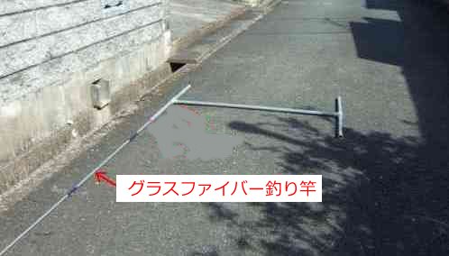
Next, cut out 25mm inner diameter PVC pipes according to the dimensions shown in the diagram below and assemble them into an H-shape. Use PVC pipe adhesive to firmly secure the pipe connections so they do not come loose.Insert the fiberglass fishing rods into the four ends of the completed H-shaped PVC pipe. There will be a small gap at this point, so wrap vinyl tape around the base of the fishing rod several times and adjust it so that it fits snugly into the PVC pipe.
After inserting the fishing rod, wrap vinyl tape around the stepped part to secure it so that it does not slip through. It is best to use a fishing rod that is 4.5m long and approximately 60cm long when retracted. If you use a 4.5m rod, cut off the thin part at the end. If you cannot get a 4.5m fishing rod, a 3.7m fishing rod should work as the longer element on one side is 3.3m long.
Final assembly
Fix the element made from the 300Ω feeder wire made in the previous section to the completed element support unit with vinyl tape. Vinyl tape at intervals of about 20 cm is sufficient for fixing.
The role of balun and how to make it
The ZL Special Antenna is a balanced antenna with left-right symmetry. On the other hand, the coaxial cable it connects to is structurally unbalanced. The role of the balun is to mediate between these two.The feed point impedance of the 2ELZL Special is said to be approximately 90 ohms. A feeder connected to this generally uses a 50 ohm coaxial cable, so connecting it as is will result in a mismatch, meaning a high SWR (SWR=1.8). The matching circuit (right side of the diagram below) corrects this impedance discrepancy.
This section explains baluns and matching circuits. The specific method for creating them is shown in the diagram below. When using a 75 Ω coaxial cable for the feeder with 2EL, only the balun is used. When using a 50 Ω coaxial cable, a matching circuit is also connected immediately after the balun.
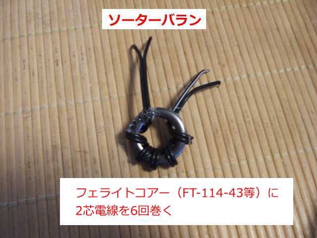
The balun on the left in the diagram below is a forced balun, and the one in the middle photo is a sorter balun. Forced baluns have better characteristics, but the winding method is more complicated, so sorter baluns, which are easier to wind, can also be used without any problems. It is up to you to decide whether to use a forced balun or a sorter balun.
Also, if you don't want to go to the trouble of making this balun and 50:75Ω matching circuit, I think it will still work if you just connect a 50Ω coaxial cable directly to the power feed point of the 300Ω feeder line without making them. If you don't, it's likely that the beam pattern will be distorted and the SWR value will be slightly higher. It may be a good idea to make it without the balun and matching circuit for now, and then add a balun or matching circuit based on the results.
*Click on the image below to enlarge it.
*The method for making the above 50:75Ω conversion circuit is explained in detail in the 50MHz 2EL ZL Special Antenna section .
Side view of installation on the mast
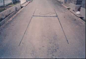
When attaching the completed antenna to a mast, since the boom part is made of PVC pipe, it is suspended with a nylon rope as shown in the diagram below for reinforcement. When used for mobile operation, the antenna itself is lightweight, so it can be installed directly on the mast without suspending it with a nylon rope and can be used without any problems.I received a production report from JH6SNG, to whom I previously sent data on the ZL special antenna , saying that when they built it for mobile use, it was very FB .
How to convert from 2EL to 3EL
By adding one 6.15m long element (director) to a 2ELZL Special, it can be converted to a 3EL ZL Special. The front gain is calculated to be about 3dB higher than that of a 2EL. At the same time as the gain is increased, the beam pattern narrows in the front direction, greatly improving performance as a beam antenna. The drawback is that the antenna itself becomes larger, but if you have the installation space, we highly recommend converting it to a 3EL.The modification will be made by using the 2EL element made in the previous section as it is. However, in order to convert it to a 3EL, the 2EL element will need to be shortened slightly. Please refer to the diagram below for the specific shortening dimensions.
Element dimensions (3EL)
The dimensions of each part of the 3ELZL Special are shown in the diagram below. To maximize the front gain, a wide-space type is used, with the distance between the director (De) and radiator (Ra) set to 2.8m (0.2λ). The dimensions shown in the diagram are for a wide space.The 2EL part will be used as is, but the length of the radiator (Ra) needs to be changed to 6.36m and the length of the reflector (Rf) needs to be changed to 6.61m. The front gain and FB ratio are calculated using the antenna calculation software MMPC (created by OM Matsuda, JA1WXB).
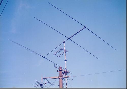
Director (De) installation position and overall assembly side view
The diagram below shows a side view of the 3ELZL Special. The boom is made of a 30mm diameter metal pipe used for wiring work. The 2EL ZL Special is secured to this boom using a clamp, as if hanging it. You can see the secured state in the photo in the next section.The director (De) is made by inserting two fishing rods into a 50cm long PVC pipe, and fixing elements made from 6.15m long 300Ω feeder wires (short-circuited at both ends) to the fishing rods with vinyl tape at approximately 20cm intervals. If the completed director (De) is installed 2.8m away from the 2ELZL Special, it will become a 3ELZL Special antenna.
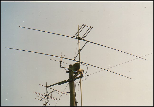
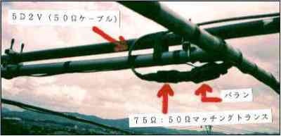
Balun and matching transformer installation status
The photo below shows the balun and matching transformer placement, and also shows the 2ELZL Special clamped to the metal boom.
ZL Special Antenna Characteristics (Computer Calculation Results)
For the 3EL calculations, I used the antenna calculation software MMPC HB9CV, and repeated calculations to optimize the front gain and F/B ratio. From the calculation results, I adopted the element data that seemed optimal and built my own antenna. By the way, the computer I used for the calculations at the time was an NEC PC-9800 series, with a clock frequency in the 60MHz range, as I recall. The table below is a study document from 1995. From several calculation results, I actually built the one in the top row, and used that 3EL ZL Special to chase DX stations.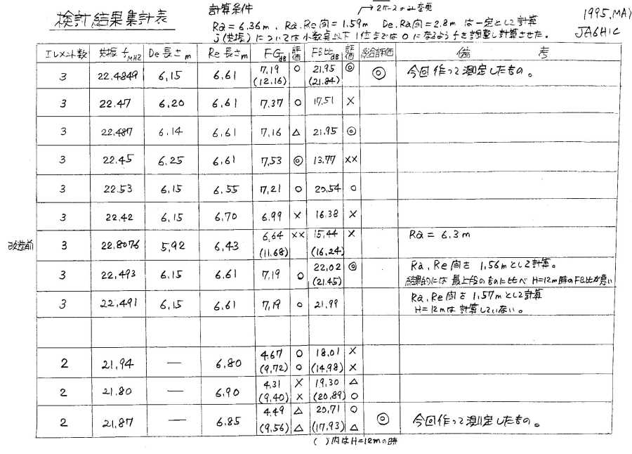
On the NEC computer I used for the calculations (which at the time had decent processing power), it took about 50 minutes to complete one calculation. Time has moved on, and on my current 2.6GHz i5 computer, the calculation results appear as soon as I press the enter key. I feel nostalgic for the days when I would wait impatiently for each calculation to finish, and I also appreciate the wonder of technological innovation.
Characteristics of the 3EL ZL Special Antenna (measured results)
The SWR characteristics and pattern shown below are for the 3ELZL Special I built. I measured the SWR using the American-made RF-1 meter, a homemade SWR meter, and, just to be safe, a Japanese-made SWR meter. All measurements were taken very close to the mast-mounted antenna. The SWR measurement results showed a flat SWR value of 1.1 between 21.000 MHz and 21.300 MHz. The SWR value at the band edge of 21.450 MHz was 1.2. My local fellow builder, JA6DWO (Mr. Hanamura), built a 3EL ZL Special using the exact same element data, and I heard it had similar SWR characteristics.
Measurements of the 2EL's SWR characteristics were planned, but due to various circumstances, they were left unmeasured. The antenna was then completely rebuilt in June 2022, and a final measurement was conducted at that time. The 2EL's SWR characteristics were a flat SWR of 1.0 between 21.005 MHz and 21.300 MHz, with an SWR of 1.05 at the band edge of 21.445 MHz. Please see the "Renewed ZL Special Antenna" section for the SWR measurement results for the 2EL.
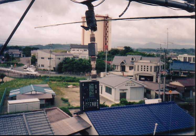
*Click on each photo to enlarge it Checking the resonance frequency with
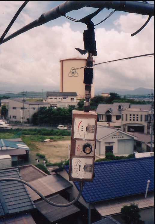
an American-made analyzer RF-1Place the SWR meter on a pole and
measure the SWR directly under the antenna.Measured beam pattern
diagram of 3EL ZL SpecialThe SWR measurement results
are shown in the table below